CHAPTER 8 USB FUNCTION
User’s Manual U12978EJ3V0UD
125
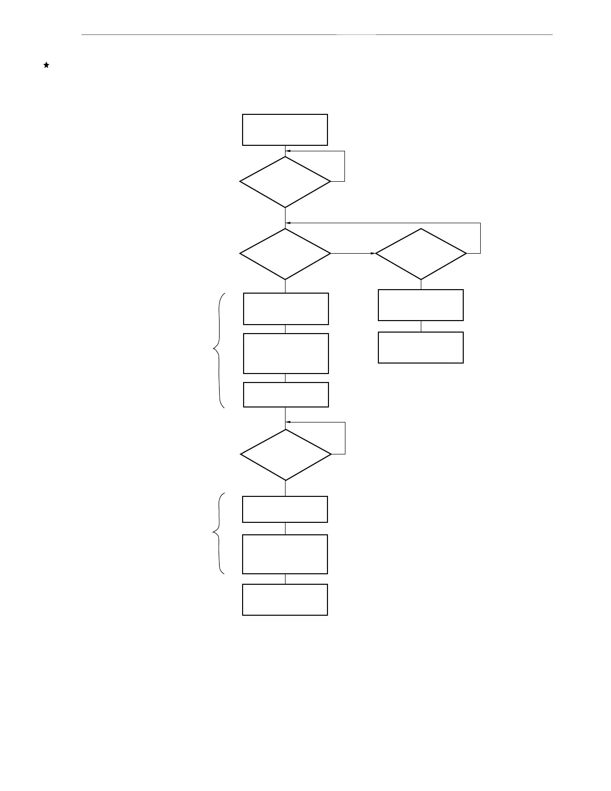
8.5.2 Remote wakeup control operation
Figure 8-21. Flow Chart of Remote Wakeup Control Operation
Idle state
Y
N
Y
10 ms to 15 ms
elapsed?
N
Resume output
started?
Y
N
A ← 00000111B
PULLEN = 1
WAKEUP = 1
PULLDP = 0
PULLDM = 1
PULLDP = 0
PULLDM = 1
PULLEN =0
PULLDP = 0
PULLDM = 1
Resume
output
Note 1
WAKEUP = 0
Idle state
Y
N
Is bus idle
duration longer
than 5 ms?
REMWUP ← A
Did HOST
output USB reset or
Resume?
Idle state
Resume output
completion
Note 2
PULLDP: Bit 2 of remote wakeup control register (REMWUP)
PULLDM: Bit 3 of remote wakeup control register (REMWUP)
PULLEN: Bit 1 of remote wakeup control register (REMWUP)
WAKEUP: Bit 0 of remote wakeup control register (REMWUP)