CHAPTER 7 WATCHDOG TIMER
User’s Manual U12978EJ3V0UD
93
7.3 Registers Controlling Watchdog Timer
The following two registers are used to control the watchdog timer.
• Timer clock select register 2 (TCL2)
• Watchdog timer mode register (WDTM)
(1) Timer clock select register 2 (TCL2)
This register sets the watchdog timer count clock.
TCL2 is set with an 8-bit memory manipulation instruction.
RESET input sets TCL2 to 00H.
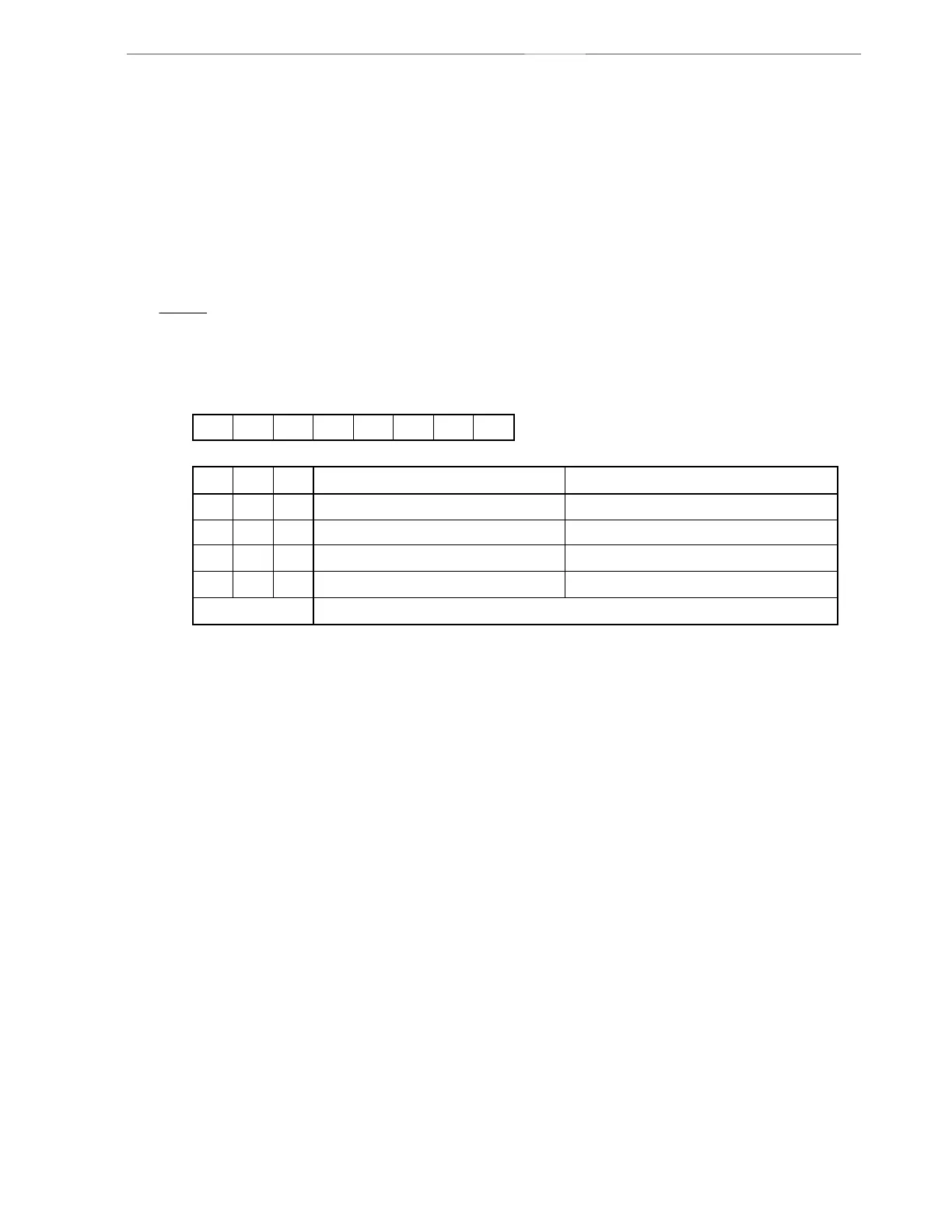
Figure 7-2. Format of Timer Clock Select Register 2
TCL22
0
0
1
1
00000TCL22 TCL21 TCL20TCL2
R/W
R/W
76543210
TCL21
0
1
0
1
f
X/2
4
fX/2
6
fX/2
8
fX/2
10
2
11
/fX
2
13
/fX
2
15
/fX
2
17
/fX
TCL20
0
0
0
0
Settings prohibited
Symbol
Address
FF42H 00H
After reset
Other than above
Watchdog timer count clock selection Interval time
(341 s)
(1.37 ms)
(5.46 ms)
(21.8 ms)
µ
(375 kHz)
(93.8 kHz)
(23.4 kHz)
(5.86 kHz)
Remarks 1. fX
: System clock oscillation frequency
2. The parenthesized values apply to operation at f
X
= 6.0 MHz.