CHAPTER 5 CLOCK GENERATOR
User’s Manual U12978EJ3V0UD
74
5.3 Register Controlling Clock Generator
The clock generator is controlled by the following register.
• Processor clock control register (PCC)
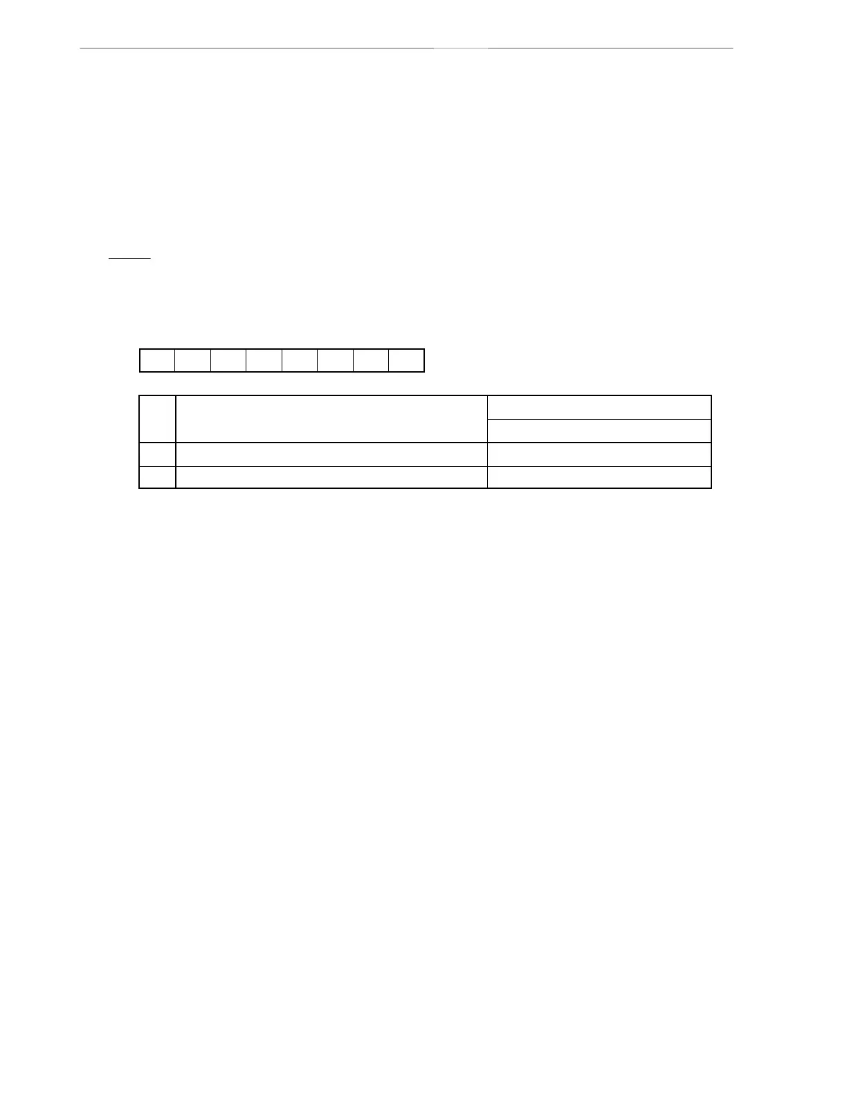
(1) Processor clock control register (PCC)
PCC selects the CPU clock and sets the of division ratio.
PCC is set with a 1-bit or 8-bit memory manipulation instruction.
RESET input sets the PCC to 02H.
Figure 5-2. Format of Processor Clock Control Register
CPU clock (fCPU) selection
000000PCC1 0PCC
Symbol Address After reset R/W
FFFBH 02H R/W
76543210
PCC1
0
1
f
X
fX/2
2
µ
µ
Minimum instruction execution time: 2/fCPU
0.33 s
1.33 s
fX = 6.0 MHz operation
Caution Bits 0 and 2 to 7 must be set to 0.
Remark fX
: system clock oscillation frequency