CHAPTER 9 SERIAL INTERFACE 10
User’s Manual U12978EJ3V0UD
158
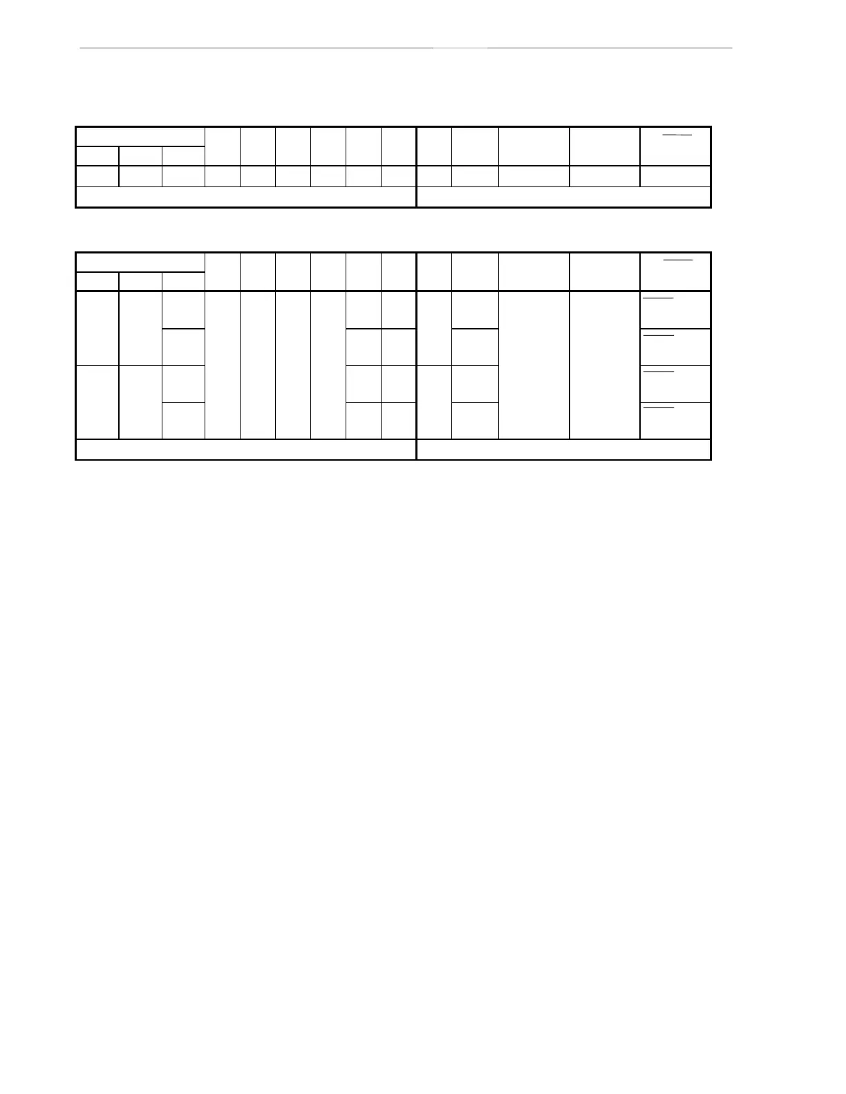
Table 9-2. Operating Mode Settings of Serial Interface 10
(1) Operation stop mode
CSIM10 PM22 P22 PM21 P21 PM20 P20 Start Shift P22/SI10 P21/SO10 P20/SCK10
CSIE10 DIR10 CSCK10 Bit Clock Pin Function Pin Function Pin Function
0 ×××
Note 1
×
Note 1
×
Note 1
×
Note 1
×
Note 1
×
Note 1
——P22 P21 P20
Other than above Setting prohibited
(2) 3-wired serial I/O mode
CSIM10 PM22 P22 PM21 P21 PM20 P20 Start Shift P22/SI10 P21/SO10 P20/SCK10
CSIE10 DIR10 CSCK10 Bit Clock Pin Function Pin Function Pin Function
1001
Note 2
×
Note 2
011× MSB External
clock
SI10
Note 2
SO10
(CMOS output)
SCK10 input
1 0 1 Internal
clock
SCK10 output
110 1× LSB External
clock
SCK10 input
1 0 1 Internal
clock
SCK10 output
Other than above Setting prohibited
Notes 1. Can be used as port function.
2. If used only for transmission, can be used as P22 (CMOS input/output).
Remark ×: don’t care