CHAPTER 6 8-BIT TIMER/EVENT COUNTERS 00 AND 01
User’s Manual U12978EJ3V0UD
80
(3) Square wave output
A square wave of arbitrary frequency can be output.
Table 6-3. Square Wave Output Range of 8-Bit Timer/Event Counter 01
Minimum Pulse Width Maximum Pulse Width Resolution
2
4
/f
X
(2.67
µ
s) 2
12
/f
X
(682.7
µ
s) 2
4
/f
X
(2.67
µ
s)
2
8
/f
X
(42.7
µ
s) 2
16
/f
X
(10.9 ms) 2
8
/f
X
(42.7
µ
s)
Remarks 1. fX
: System clock oscillation frequency
2. The parenthesized values apply to operation at f
X
= 6.0 MHz
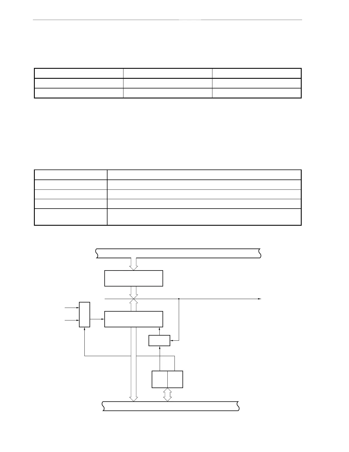
6.2 Configuration of 8-Bit Timer/Event Counters 00 and 01
8-bit timer/event counters 00 and 01 consist of the following hardware.
Table 6-4. Configuration of 8-Bit Timer/Event Counters 00 and 01
Item Configuration
Timer counter 8 bits × 2 (TM00 and TM01)
Register Compare register: 8 bits × 2 (CR00 and CR01)
Timer outputs 1 (TO01)
Control registers 8-bit timer mode control registers 00 and 01 (TMC00 and TMC01)
Port mode register 2 (PM2)
Figure 6-1. Block Diagram of 8-Bit Timer 00
Internal bus
8-bit compare register 00
(CR00)
Match
INTTM00
f
X
/2
6
f
X
/2
9
Selector
Clear
8-bit timer counter 00
(TM00)
Internal bus
TCE00
TCL000
8-bit timer mode control register 00 (TMC00)
Selector