CHAPTER 2 PIN FUNCTIONS
User’s Manual U12978EJ3V0UD
33
2.3 Pin I/O Circuits and Recommended Connection of Unused Pins
Table 2-1 lists the types of I/O circuits for each pin and explains how unused pins are handled.
Figure 2-1 shows the configuration of each type of I/O circuit.
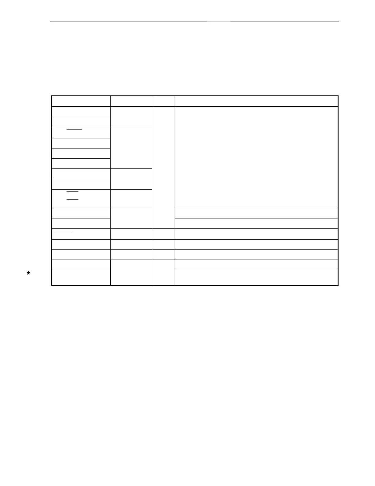
Table 2-1. Type of Pin I/O Circuit Recommended Connection of Unused Pins
Pin Name I/O Circuit Type I/O Recommended Connection of Unused Pins
P00 to P07
P10 to P17
5-R
P20/
SCK10
P21/SO10
P22/SI10
P23, P24
8-C
P25
P26/INTP0/TI01/TO01
8-F
P40/
KR00 to
P47/
KR07
8-C
Input: Independently connect to V
DD0
, V
DD1
, V
SS0
, or V
SS1
via a
resistor.
Output: Leave open.
USBDM Connect to the REGC pin.
USBDP
24-A
I/O
Independently connect to V
SS0
or V
SS1
via a resistor.
RESET
2 Input —
NC ——Leave open.
REGC ——Connect to USBDM pin.
IC Connect directly to V
SS0
.
V
PP
——
Independently connect a 10 kΩ pull-down resistor, or connect directly
to V
SS0
.