CHAPTER 4 PORT FUNCTIONS
User’s Manual U12978EJ3V0UD
62
4.2.3 Port 2
This is a 7-bit I/O port with an output latch. Port 2 can be specified in the input or output mode in 1-bit units by
using port mode register 2 (PM2). When using the P20 to P26 pins as input port pins, on-chip pull-up resistors can
be connected in 7-bit units by using pull-up resistor option register 0 (PU0).
When P25 or P26 is used, CMOS output or N-ch open-drain output can be specified in 1-bit units by using port
output mode register 1 (POM1).
The port is also used as a data I/O and clock I/O to and from the serial interface, timer I/O, and external interrupt.
This port to set to the input mode when the RESET signal is input.
Figures 4-4 through 4-9 show block diagrams of port 2.
Caution When using the pins of port 2 as the serial interface, the I/O or output latch must be set
according to the function to be used. For how to set the latches, see Table 9-2.
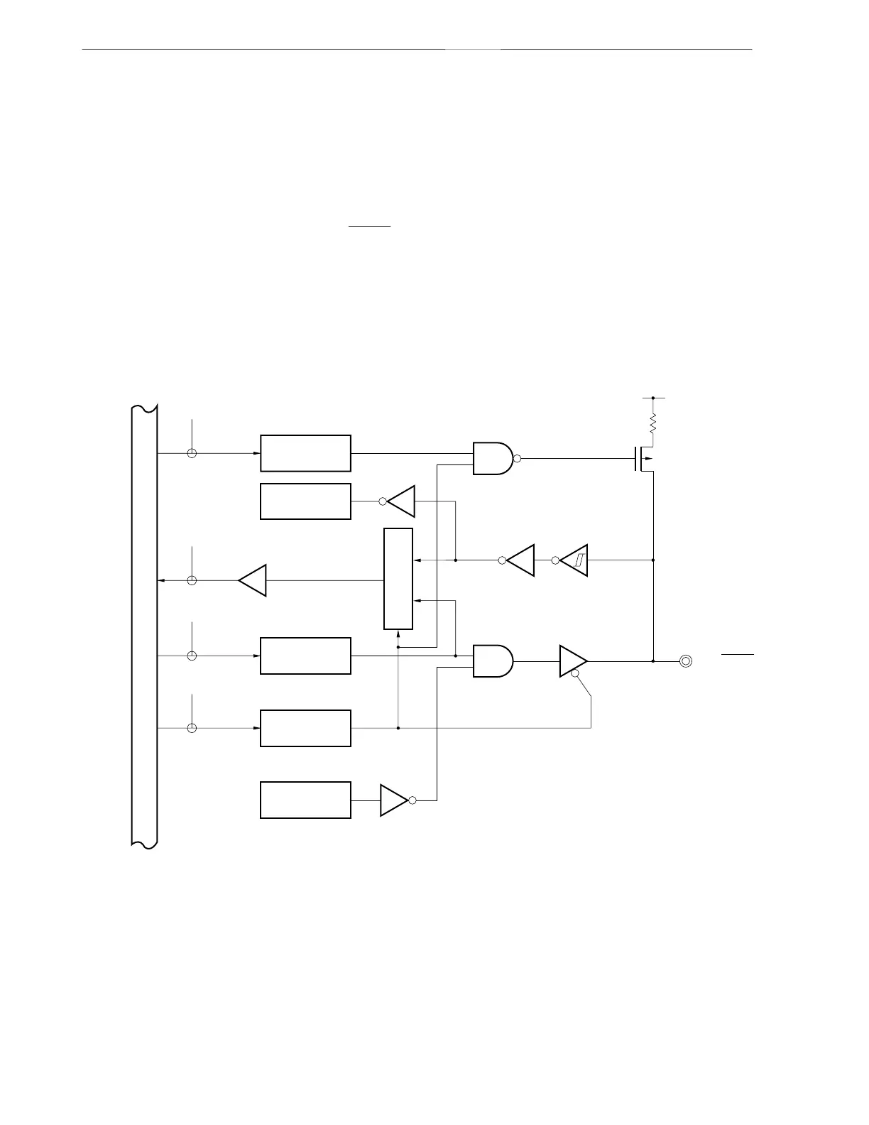
Figure 4-4. Block Diagram of P20
PU0: Pull-up resistor option register 0
PM: Port mode register
RD: Port 2 read signal
WR: Port 2 write signal
Internal bus
VDD0
P-ch
P20/SCK10
WR
PU0
RD
WR
PORT
WRPM
PU02
Alternate
function
Output latch
(P20)
PM20
Alternate
function
Selector