CHAPTER 9 SERIAL INTERFACE 10
User’s Manual U12978EJ3V0UD
159
9.4 Operation of Serial Interface 10
Serial interface 10 provides the following two modes.
• Operation stop mode
• 3-wire serial I/O mode
9.4.1 Operation stop mode
In the operation stop mode, serial transfer is not executed; therefore, the power consumption can be reduced.
The P20/SCK10, P21/SO10, and P22/SI10 pins can be used as normal I/O ports.
(1) Register setting
Operation stop mode is set by serial operation mode register 10 (CSIM10).
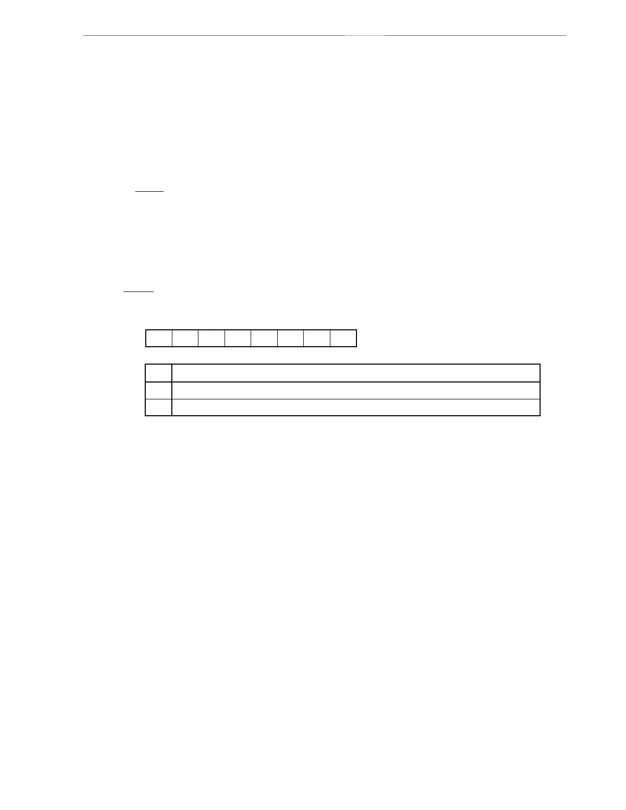
Serial operation mode register 10 (CSIM10)
CSIM10 is set with a 1-bit or 8-bit memory manipulation instruction.
RESET input sets CSIM10 to 00H.
CSIE10
0
1
Operation control in 3-wire serial I/O mode
CSIE10
00
TPS100
0 DIR10
CSCK10
0CSIM10
Symbol
Address After reset R/W
FF72H 00H R/W
<7>6543210
Operation disabled
Operation enabled
Caution Bits 0, 3, 5, and 6 must be set to 0.