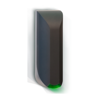
uPASS Target | installation guide
22/
3.3 Digital I/O
3.3.1 General purpose inputs / LED and relay control
Relay output
The relay is by default set to automatic mode. The relay is activated for every tag read and stays activated for the tag
hold time (see chapter 6.4.3). If the automatic mode is switched off, the relay is operated by input 1.
LED
The front LED need to be configured as Remote (see chapter 6.4.4) to control them by the input pins. Input1 controls
the “UnLock” (UL) color of the LED and input 2 controls the Not Authorized (NA) color of the LED.
Inputs
Two general-purpose inputs are available of CONN. 2. The inputs can control the LED at the front of the reader to
provide feedback and a relay for switching devices (for example doors or gates).
TRANSIT compatible mode
In TRANSIT compatible mode the inputs and outputs are controlled by the TRANSIT compatible processor. See
TRANSIT firmware guide for more details.
OSDP firmware
Upon input status change, the reader will send input status report message OSDP_ISTATR. The current input status can
be requested by sending the input status report request message OSDP_ISTAT.
Use the OSDP_OUT command to control the relay output state.
19: CONN. 2
Input 1 / UL (OSDP input 0)
Input 2 / NA (OSDP input 1)
Table 5: General input connection
20: CONN. 3
Table 6: Relay connection
 Loading...