12 E2600 Controller-Drive Tray Installation Guide
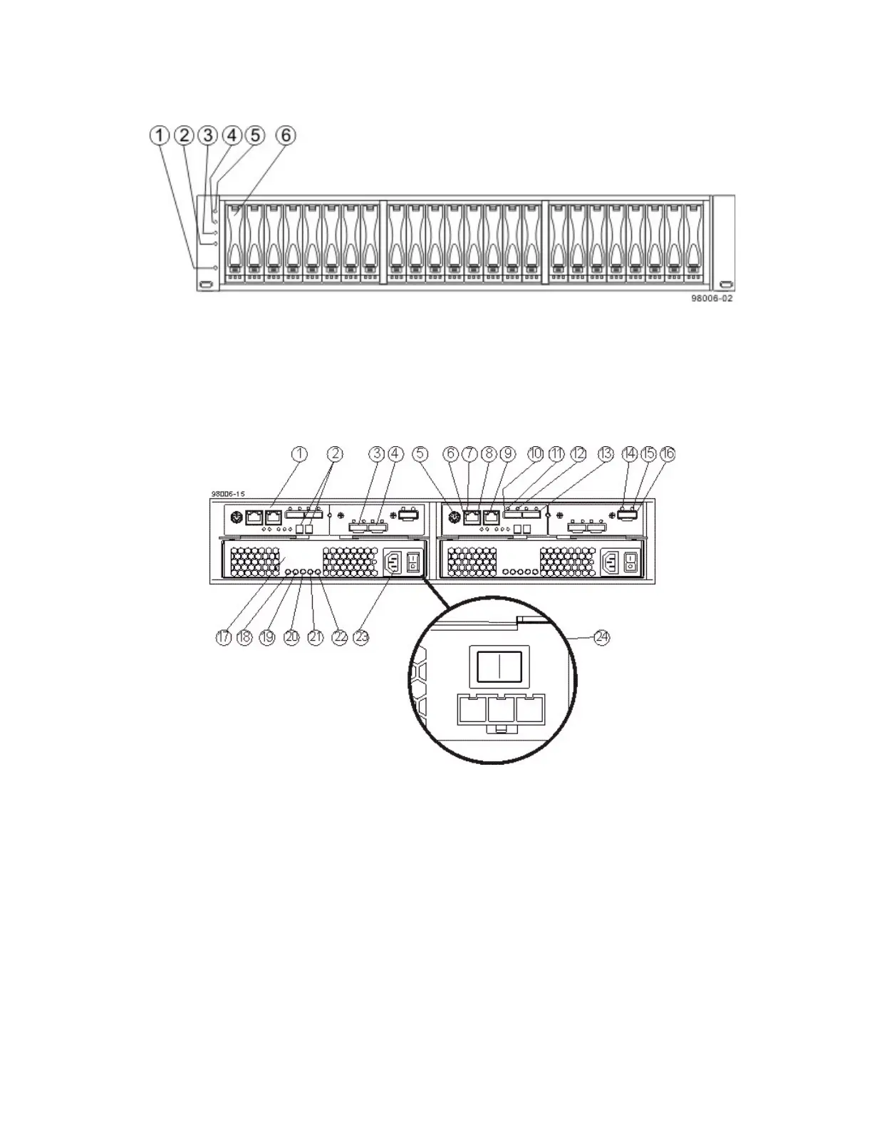
Figure 6 E2624 Controller-Drive Tray – Front View
1. End Cap Standby Power LED
2. End Cap Power LED
3. End Cap Over-Temperature LED
4. End Cap Service Action Required LED
5. End Cap Locate LED
6. Drive Canister
Figure 7 E2612 or E2624 Duplex Configuration– Rear View
1. Controller A Canister
2. Seven-Segment Display
3. Host Interface Card Connector 1
4. Host Interface Card Connector 2
5. Serial Connector
6. Ethernet Connector 1
7. Ethernet Link Active LED
8. Ethernet Link Rate LED
9. Ethernet Connector 2
10. Host SFF-8088 Connector 2 (Native)
11. Host Link 2 Fault LED
12. Host Link 2 Active LED
13. Base Host SFF-8088 Connector 1