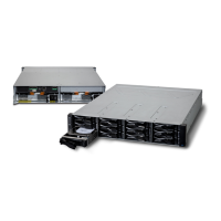
E2600 Controller-Drive Tray Installation Guide 19
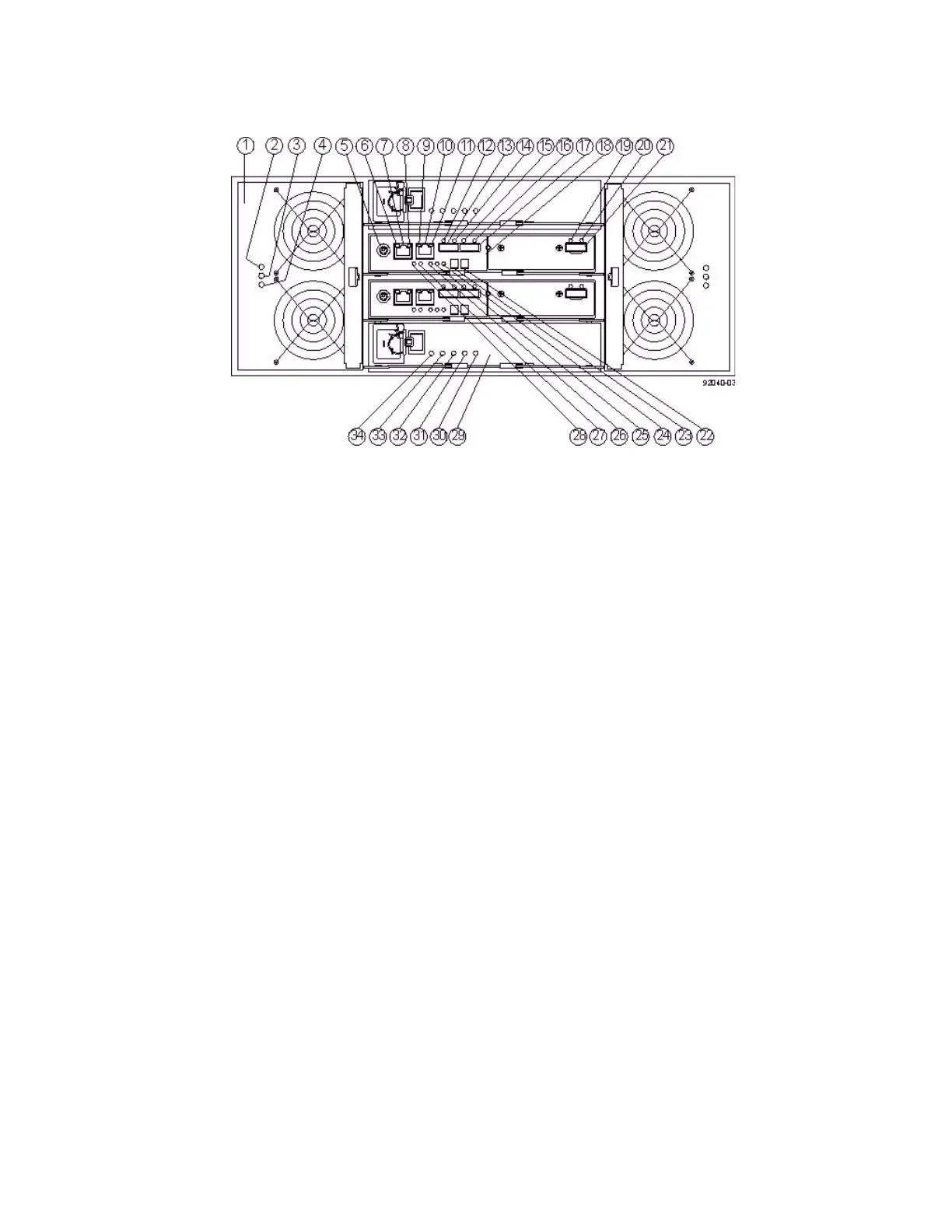
Figure 18 E2660 Controller-Drive Tray Duplex Configuration – Rear View
1. Fan Canister
2. Fan Canister Power LED
3. Fan Canister Service Action Required LED
4. Fan Canister Service Action Allowed LED
5. Serial Connector (PS2 to DB9 connector required)
6. Ethernet Link 1 Active LED
7. Ethernet Connector 1
8. Ethernet Link 1 Rate LED
9. Ethernet Link 2 Active LED
10. Ethernet Connector 2
11. Ethernet Link 2 Rate LED
12. Host Link 2 Fault LED
13. Base Host SFF-8088 Connector 2
14. Host Link 2 Active LED
15. Host Link 1 Fault LED
16. Host Link 1 Active LED
17. Base Host SFF-8088 Connector 1
18. Controller A Canister
19. ESM Expansion Fault LED
20. ESM Expansion Active LED
21. Expansion SFF-8088 Port Connector
22. Second Seven-Segment Display Field
23. First Seven-Segment Display Field
24. Cache Active LED
25. Controller A Service Ac
tion
Required LED
26. Controller A Service Action Allo
wed LED
27. Battery Service Action Required LED
28. Battery Charging LED
29. Power Canister
30. Power Canister AC Power LED
31. Power Canister Service Action Required LED