Gear units – Operating and Assembly Instructions
20 B 1000 en-2518
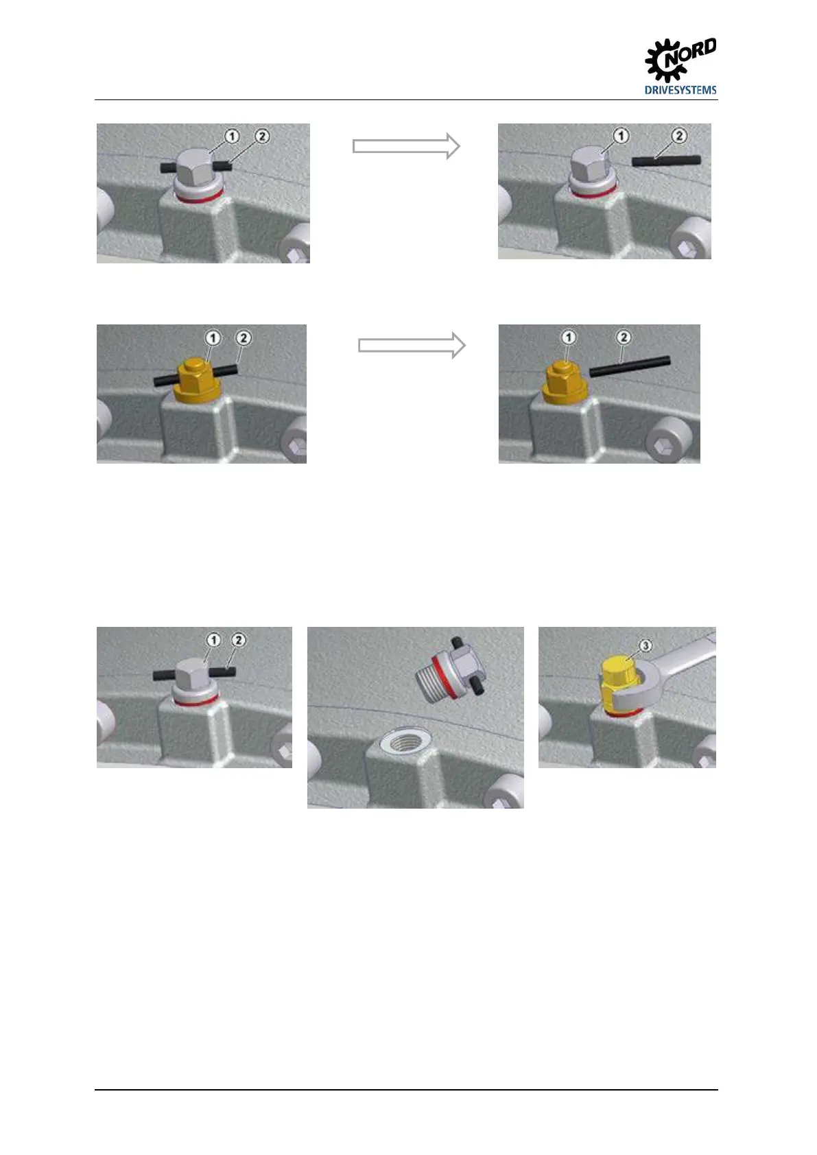
Explanation
1 Standard vent plug
2 Transport securing
device
Figure 2: Activating the vent plug
Explanation
1 Vent screw
2 Transport securing
device
Figure 3: Activating the vent plug
Before commissioning, the vent plug must be replaced with the special pressure vent which is
supplied as a loose part.
This is done by unscrewing the vent fitting and replacing it with the special pressure vent and seal
(refer to Section 6.1 "Versions and maintenance"). Double gear units consist of two single units and
are equipped with 2 oil chambers and 2 pressure vents.
Explanation
1 Standard vent plug 2 Transport securing device 3 Special pressure vent screw
Figure 4: Removing the vent plug and fitting the special pressure vent
Pos: 41 /A llg em ein/ Allg em eing ülti ge M od ule/ ---------- Seitenu mbr uch ---------- @ 1\mod_1329145698658_0.doc x @ 15891 @ @ 1
132


 To Next Page