3 Assembly instructions, storage, preparation, installation
B 1000 en-2518 25
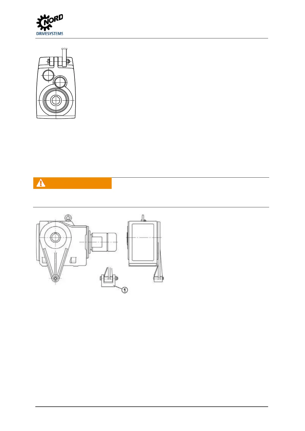
Figure 12: Mounting the rubber buffer (Option G or VG) on parallel shaft gear units
To fit the rubber buffer, tighten the screw fastening until there is no play between the contact surfaces
when there is no load.
Then turn the fastening nut half a turn in order to pre-tension the rubber buffer (only applies for screw
fastenings with adjusting threads). Greater pre-tension is not permissible
WARNING
Risk of injury
The gear unit may suddenly rotate around the shaft if the bolts are loosened.
Secure the screw fastening against loosening, e.g. with Loctite 242 or a second nut.
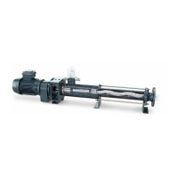
Explanation
1 Always support torque support
on both sides
Fig. 13: Attaching the torque support on bevel gear and worm gear units
Tighten the fastenings of the torque support with the correct tightening torques(please see chapter 6.5
"Torque values")and secure against loosening (e.g. Loctite 242, Loxeal 54-03).
137