Gear units – Operating and Assembly Instructions
28 B 1000 en-2518
Pos: 46 /A nl eitu nge n/G etr iebe /3. Mont ag e, L ager ung , V orb erei tung , Aufst ell ung /Mo ntag e v on Abdeckhauben [B1000] (2018-07- 17 13: 50:13) @ 3\mod_1369220109363_388.docx @ 70563 @ 2 @ 1
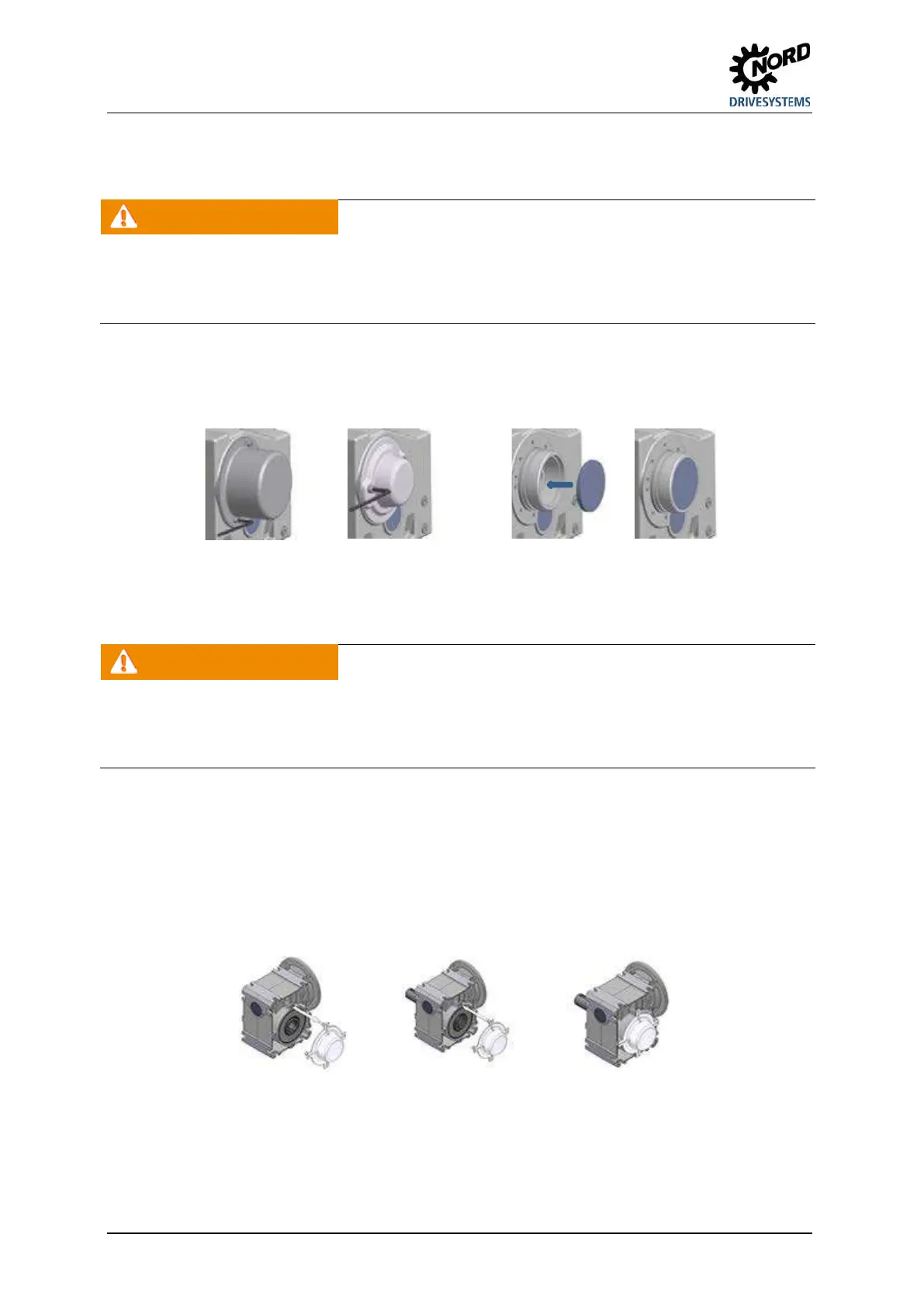
3.9 Fitting the covers
WARNING
Risk of injury
There is a danger of injury due to shrink discs and freely rotating shaft journals.
• Use a cover (Option H and Option H66) as a guard.
• If this does not achieve sufficient protection against contact according to the required protection type, the
machinery and plant constructor must ensure this by means of special attached components.
All fixing screws must be used and tightened to the correct torque(please see chapter 6.5 "Torque
values"). For covers with Option H66, press in the new / new condition closing cap by tapping it lightly
with a hammer.
Figure 15: Fitting the covers, Option SH, Option H, and Option H66
Pos: 47 /A nl eitu nge n/G etr iebe /3. Montage, Lagerung, Vorbereitung, Aufstellung/Montage von Abdeckkappen [B1000] (2018-07-17 1 3:51: 52) @ 5\mod_1410510888133_388.docx @ 149064 @ 2 @ 1
3.10 Fitting the covers
WARNING
Risk of injury
There is a danger of injury due to freely rotating shaft journals.
• Use a cover cap as a guard
• If this does not achieve sufficient protection against contact according to the required protection type, the
machinery and plant constructor must ensure this by means of special attached components.
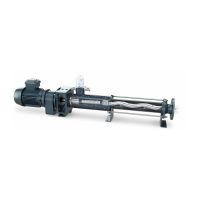
Many versions of the universal worm gear unit are supplied with plastic cover caps as standard. These
cover caps protect the shaft sealing ring against the entry of dust and other possible contamination.
The cover caps can be removed by hand without the use of tools and pushed onto the A or B side.
The cover cap must be removed before installing the universal worm gear unit. After installation is
complete, the cover cap must be pushed into the threaded holes on the output flange on the
corresponding side. Care must be taken that the cover cap is removed and pushed on vertically, in
order not to damage the expansion elements of the cover cap.
Fig. 16: Removal and fitting of the cover cap
140