Motors – Operating and Assembly Instructions
14 B 1091 en-3118
Pos: 27 /A nl eitu nge n/M otor en/ B10 91 D re hstro mm otor en/ 1. Al lg em eines /Au sri cht en @ 7\ mod_1431349204216_388.docx @ 217522 @ 3 @ 1
1.3.4 Alignment
In particular with direct coupling, the motor shafts and the driven machine must be axially and radially
aligned to each other. Incorrect alignment may result in damage to the bearings, excessive vibration
and breakage of the shaft.
Pos: 28 /A nl eitu nge n/M otor en/ B10 91 D re hstro mm otor en/ 1. Al lg em eines /Ab tri ebs wel len @ 1 0\mod_1455023853692_388.docx @ 289540 @ 3 @ 1
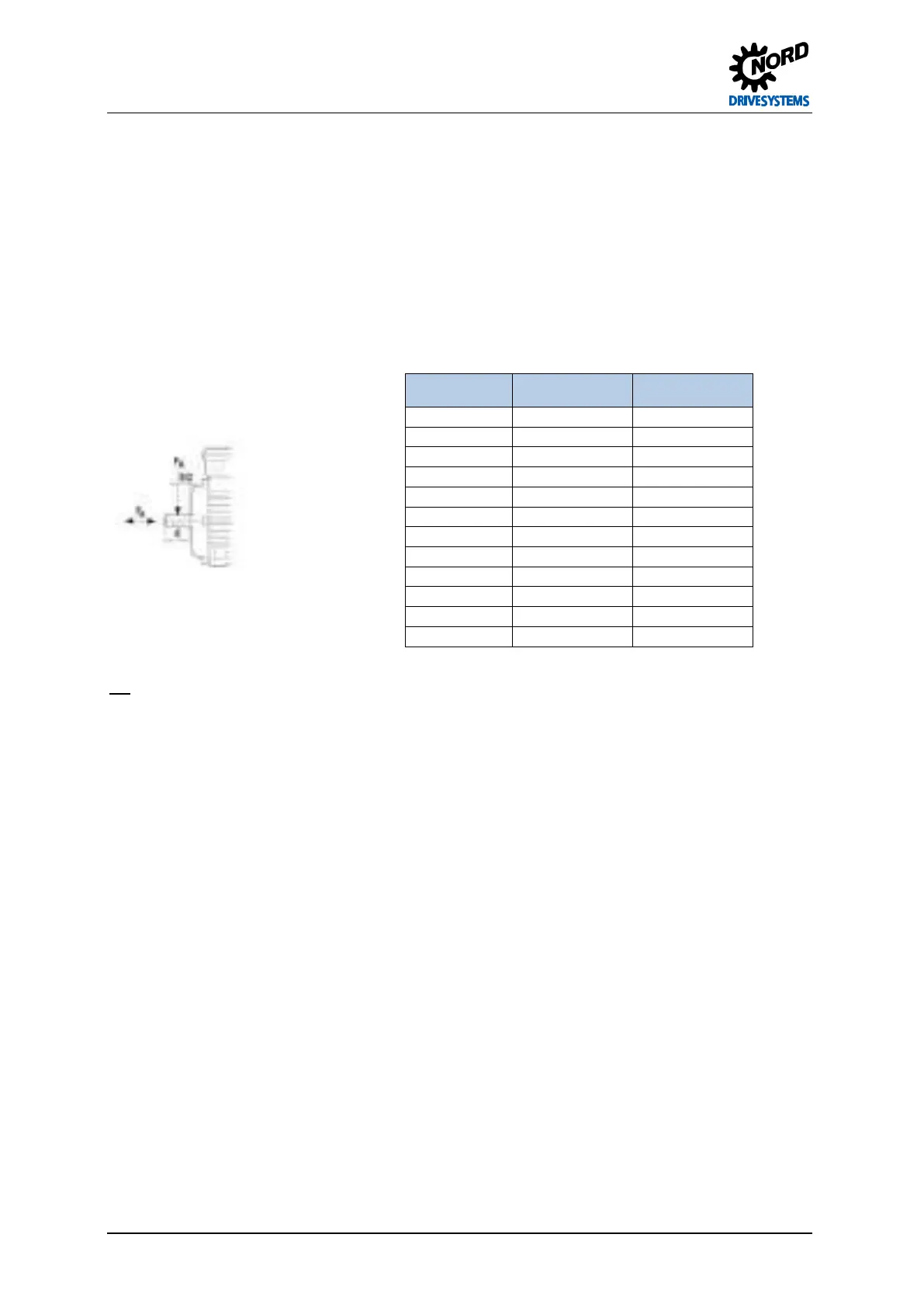
1.3.5 Output shafts
The maximum permissible axial (F
A
) and radial forces (F
R
) for the A side end of the motor shaft can be
obtained from the table below. Getriebebau NORD should be consulted if the radial force (F
R
) is applied
at a distance which is greater than the length E/2.
Type
F
R
[N]
F
A
[N]
63 530 480
71 530 480
80 860 760
90 910 810
100 1300 1100
112 1950 1640
132 2790 2360
160 3500 3000
180 .X 3500 3000
180 5500 4000
200 .X 5500 4000
225 8000 5000
No axial (F
A
) and radial forces (F
R
) are permissible for the B side shaft end.
NOTICE! Attachments must not cause rubbing (danger of excessive temperatures and sparking) or
impair the necessary flow of cooling air.
Pos: 29 /Allgemein/Allgemeingültige Mod ule/---------- Sei tenu mbruc h ---------- @ 1\mod_1329145698658_0.docx @ 15891 @ @ 1
198
 Loading...