3 Assembly instructions, storage, preparation, installation
B 1000 en-2518 31
Pos: 49 /A nl eitu nge n/G etr iebe /3. Mont ag e, L ager ung , V orb erei tung , Aufst ell ung /Mo ntag e d er K ühl schl ang e an das K ühls yst em [ B10 00_2 000 ] (2 018- 07- 17 13: 54:44) @ 3\mod_1369223912136_388.doc x @ 70805 @ 2 @ 1
3.12 Fitting the cooling coil to the cooling system
WARNING
Risk of injury
Possibility of injury due to pressure discharge.
Ensure that the pressure is released from the cooling circuit before carrying out any work on the gear unit.
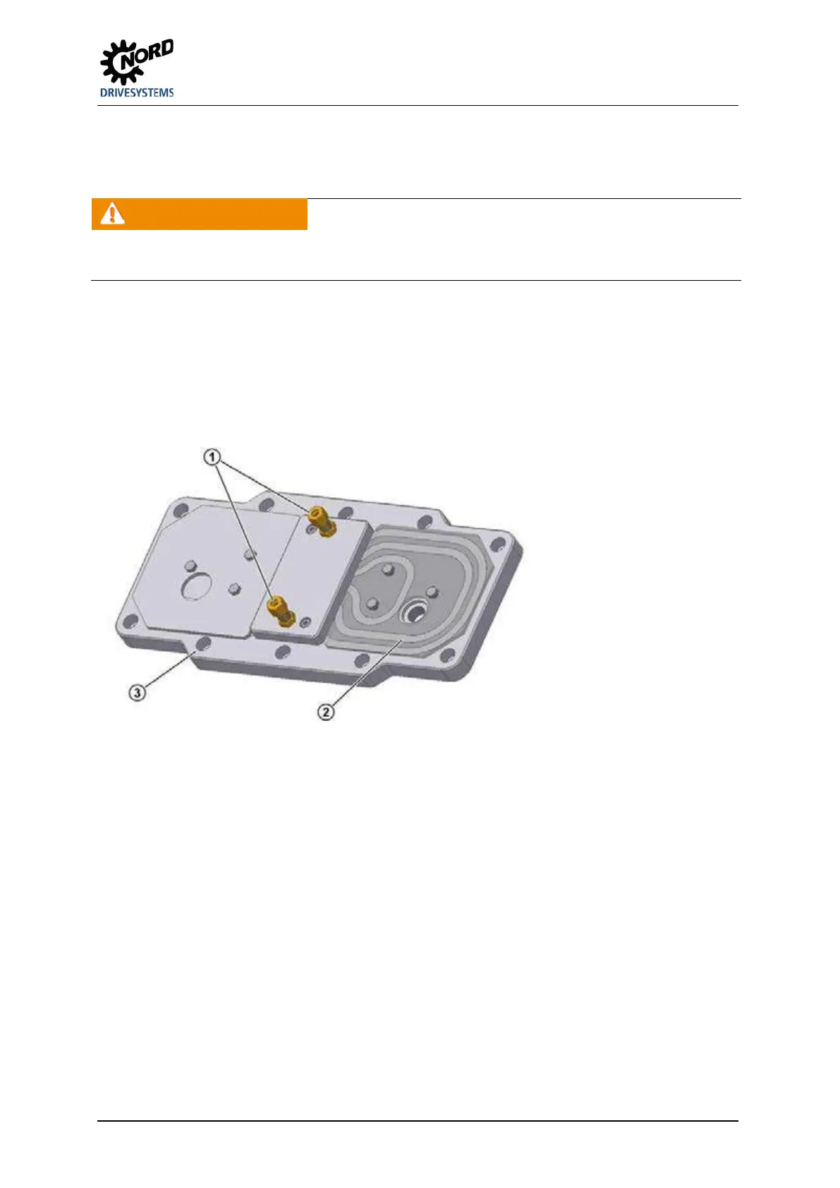
The cooling coil is installed in the casing cover. Cutting ring screw threads according to DIN 2353 are
located at the casing cover for the connection of a pipe with an external diameter of 10 mm.
Remove the closing cap from the screw neck prior to assembly to avoid any contamination of
the cooling system. The screw necks should be connected with the coolant circuit, which must be
provided by the operator. The flow direction of the coolant is irrelevant.
Make sure not to twist the screw necks during or after assembly as the cooling coil may be
damaged. It must be ensured that no external forces act on the cooling coil.
Explanation
1 Cutting ring screw threads
2 Cooling coil
3 Housing cover
Figure 18: Cooling cover
143


 To Next Page