31
TXFL200 RX
1
2345678910
11
12
14
13
PHOTOTEST
OUT1
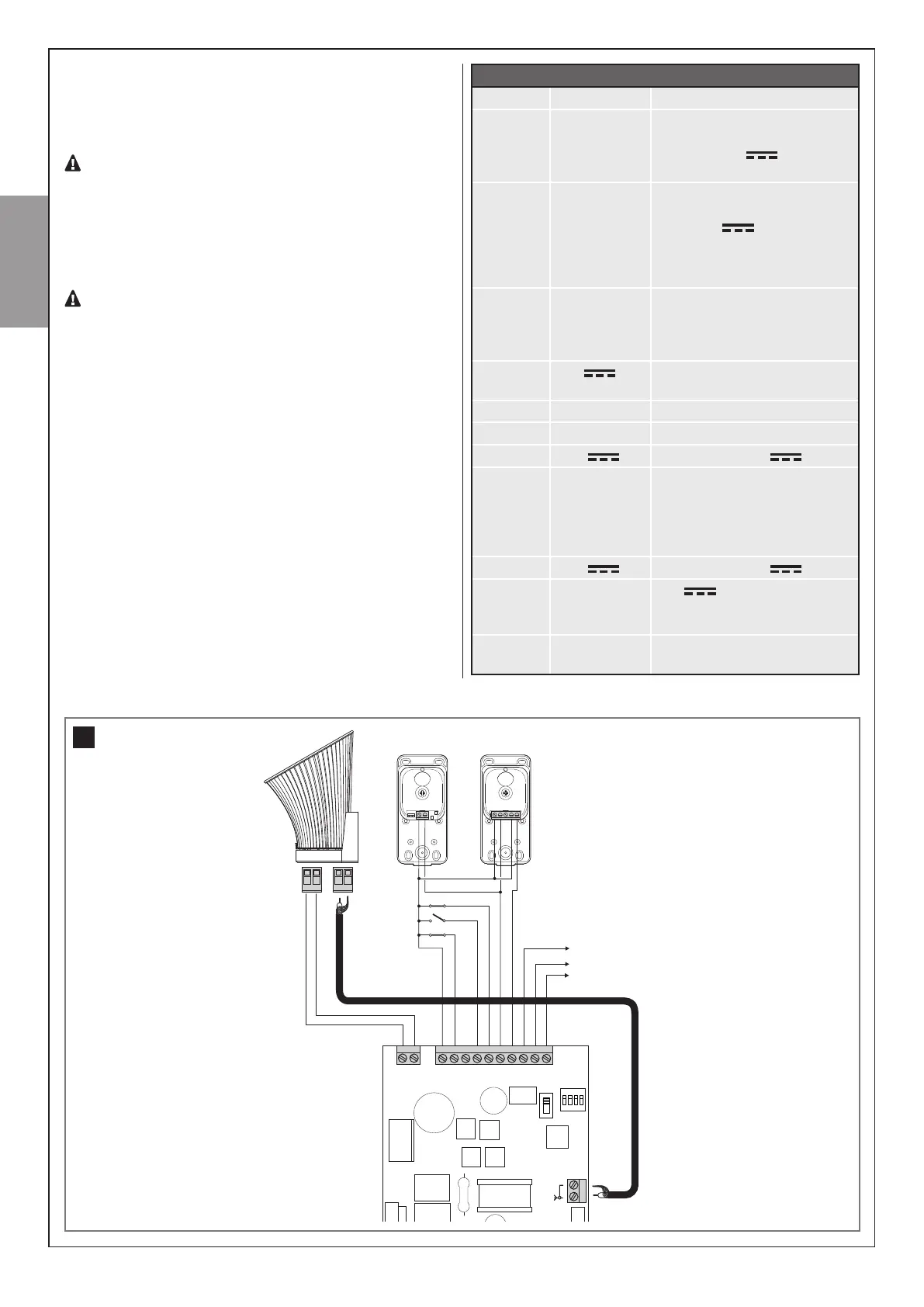
3.5 – DESCRIPTION OF THE ELECTRICLA CONNECTIONS
Thefollowingisabriefdescriptionoftheelectricalconnections(table
5
- g.31
);forfurtherinformation,pleasereadsection9(“Devices
connectabletothecontrolunit”).
TIMER FUNCTION: if START contact is kept closed (for
instance through a timer-controlled or bistable relay), con-
trol unit opens the door and leaves the door opened. The
automation does not accept closing commands (neither
automatic nor wired) until START contact is reopened.
In this mode, dip switch 1 STEP is set to OFF and dip 2
AUTO to ON to ensure that the gate never remains locked
open.
If START contact is kept closed during the control unit
starting after a blackout, the door will immediately execute
the start command.
Table 5
Terminals Function Description
1 - 2 OUT1
Commandoutputbythe
transmitterbutton.Volt-freerelay
contactfor24V
max3W
loads.
3 Phototest 24Voutputforsafetytest.This
connectioncanbeusedinstead
ofthe24V
to connect
thepowersupplyoftheTX
photocellortheresistiveS1
edge
4 S2 Photo Inputforsafetydevices,
normallyclosedcontact.
Function associated to dip
switchFunc
5 0 V
Negative terminal for
accessories devices connected
6 Stop Stop,normallyclosedcontact
7 Start Start,normallyopencontact
8 24 V
Powersupply24V
9 S1 Edge Inputforsafetyedges,normally
closedcontact.Briefmovement
inversionincaseofobstacle
duringclosingandblockofthe
movementduringopening.
10 24 V
Powersupply24V
11 - 12 Flashing 24V
max.15Washing:
aFL200ashinglightcanbe
connectedtothisoutput
13 - 14 Aerial Antennaground(13)
Antennasignal(14)
14–English
English