embedded in concrete and other preparation work for the installation can
becompletedtonalisethesitereadyforsubsequentinstallationopera-
tions.
In particular, for digging the pit used to anchor the gearmotor to
the ground, proceed as follows:
01. Digthefoundationpitinthegearmotorxturepoint(g. 3) Note – The
dimensions of the pit must be the same or greater than those of the
foundation plate.
02. Lay the ducting for the routing of cables.
CAUTION! – In general, position the ends of the ducting used for
electrical cables in the vicinity of the points envisaged for xture of
the various components.
Note: The ducting serves to protect electrical cables and prevent acciden-
tal damage in the event of impact.
To prepare the electric cables required in the system, refer to g. 11-11a
and Table 1 – Technical specications of electric cables.
TABLE 1: Technical specications of electric cables
Connection Cable type Maximum admissible
length
A:POWERCable Cable3x1,5mm
2
30 m (note 1)
B:FLASHING Cable2x0,5mm
2
30 m
LIGHT
withaerialcable RG58typeshielded 20m
cable (lessthan5mrecommended)
C:PHOTOCELL Cable2x0,5mm
2
(TX) 30 m
Cable Cable4x0,25mm
2
(RX) 30 m
D:KEY-OPERATED Cables4x0,25mm
2
30 m
SELECTOR SWITCH
cable DIGITAL
KEYPAD
General note: The cables required for the set-up of the system (not included
in the pack) may vary according to the quantity and type of devices envisaged
for the installation.
Note 1: Ifgreaterlengthsarerequired,acablewithadiameterof3x2.5mm
2
maybeused;inthiscaseearthingisrequiredinthevicinityoftheautomation
.
CAUTION! – The cables used must be suited to the installation
environment; for example a cable type H03VV-F for indoor envi-
ronments is recommended and a cable type H07RN-F for outdoor
environments is recommended.
3.5 - Installing the automation components
WARNINGS
• Incorrect installation may cause serious physical injury to those
working on or using the system.
• Before assembly of the automation, perform the preliminary
checks as described in paragraphs “3.2 – Suitability of environment
and gate to be automated” and “3.3 – Product application limits”.
• Fit one or more sheaths for routing the electric cables.
Fixing the foundation plate
IMPORTANT !– If the weight of the gate exceeds 200 kg or if used
in inadequate conditions, the foundation plate must be completely
embedded in the concrete.
There are two methods of anchoring the foundation plate to the ground:
a) if a concrete base is already present: Simply place the plate on the base
in the correct position and secure by means of screws for concrete (g. 4).
b) if there is no concrete base: Secure the plate in the concrete by means
of the two bolts on the plate (g. 5).Toxtheplate,proceedasfollows:
01. Cast concrete into the pit, ensuring that the ducting tube for electric
cablescomeoutofthesurface;
02. While the concrete is still liquid, embed the foundation plate, ensuring
that it protrudes from the concrete by its thickness.
Gearmotor installation
01. Remove the gearmotor cover using a screwdriver to loosen the lateral
screws (g. 6). Note – Leave the gearmotor without the cover until
the installation and programming phases have been completed.
02. Place the gearmotor on the foundation plate and secure by means of
therelativehexscrewsupplied(g. 7).
03. Release the gearmotor by means of the special release key (refer to
the paragraph “Manually releasing or locking the gearmotor” in the
“Operation manual”).
•Manuallymovetheleafstoanypositionandleavestationary,ensuring
that they do not move from this position and that the gate leaf remains
balanced.
•Ensurethatthereisnoriskofgateleafguidescomingoutoftheirseats.
•Ensurethatthegearmotorxingzoneisnotsubjecttotheriskofood-
ing;ifnecessaryinstallthegearmotorinapositionraisedfromtheground.
•Ensurethatthespacearoundthegearmotorenablessafeandeasy
manual gate release.
•Ensurethatthecrushingpointsbetweenthegateleafandxedpartsof
the latter are protected during the Opening and Closing manoeuvres.
•Ensurethattheselectedsurfacesforinstallationofthevariousdevic-
esaresolidandguaranteeastablexture.Inparticular,ensurethatthe
selectedsurfacesforxingthephotocellsareatandenablecorrectalign-
ment between photocells.
•Ensurethatalldevicestobeinstalledareinashelteredlocationand
protected against the risk of accidental impact.
•Ensurethattheoperatingtemperaturerangeasspeciedontheprod-
uct dataplate is compatible with the climatic conditions of the place of
installation.
•Ifthegateleafincorporatesapedestrianaccessdoororifthisdooris
positioned in the gate movement area, ensure that this does not prevent
normalgatetravel;ifnecessaryinstallacompatibleinterlocksystem.
•Connectthecontrolunittoanelectricpowerlineequippedwithanearth-
ing system.
•Onthepowerlinefromtheautomation,installadevicefordisconnec-
tion from the power mains, to guarantee a gap between contacts and
complete disconnection in the conditions of overvoltage category III. If the
powerdisconnectdeviceisnotinthevicinityoftheautomation,tablock
system against possible inadvertent or unauthorised connection.
3.3 - Product application limits
Toascertainsuitabilityoftheproductwithrespecttothespecicfeatures
of the gate and area to be automated, the following checks should be
performed as well as a check for compliance of the technical data in this
paragraph and the chapter 8 “Product technical specications”.
•Ensurethatthedimensionsandweightofthegatearewithinthefollow-
ing limits of use:
maximum length 7 m
maximum weight 500 kg
•Checktheoveralldimensionsofthegearmotorwithreferencetog. 1.
Note – These measurements also serve as a reference to calculate the spa-
ce occupied by the foundation pit for routing the electrical cable ducting.
•Ensurethatthedimensionsoftheselectedareaformountingthegear-
motor is compatible with the overall dimensions.
•Onthegateleaf,ensurethatthesurfaceformountingtherackissuitable
and solid.
Caution! – If the results of these checks do not conform to speci-
cations, this model cannot be used for automation of your gate.
3.4 - Preliminary set-up work
Fig. 2, shows an example of an automation system set up with Nice com-
ponents. These parts are positioned according to a typical standard lay-
out.
With reference to g. 2, locate the approximate position for installation of
each component envisaged in the system.
Warning -the“xed”controldevicesmustbevisiblefromthegatebut
positioned far from moving parts.
The gearmotor is factory set to be installed on the right-hand side of the
gate. CAUTION! - If forced to install the gearmotor on the left-hand
side of the gate refer to the instructions in chapter 4 (paragraph
4.1 - point 07).
Components required to set-up a complete system (g. 2):
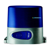
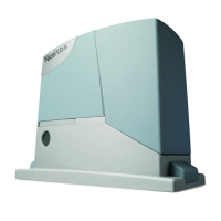
1 - electromechanical gearmotor
2 - pair of photocells
3 - key-operated selector switch or digital keypad
4-ashinglightwithincorporatedaerial
5 - limit switch brackets
6 - rack
7 - posts for phocells
Beforestartinginstallation,ensurethatthereisallequipmentandmateri-
als required for the work concerned. Also ensure that all items are in good
condition and comply with local safety standards.
Dig the routes for the ducting used for electrical cables, or alternatively
external ducting can be laid, after which the pipelines can be
2 – English
EN