tion, make the earthing connection on the terminal as shown in g. 12.
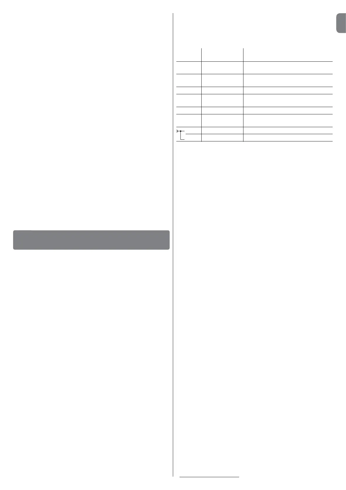
Description of electrical connections
This section describes the possible connections to the control units for
control devices and safety devices:
Terminals Function Description
1 - 2 - 3 Power supply Mains power line
4 - 5 Flashing light Outputforconnectionofashinglightto
power mains (Max. 40 W)
8 - 9 24 Vac Servicepowersupply24Vac+/-25%
(Max.150mA)
9 Common Common for all inputs
10 Alt Input with “Alt” function
(Stop and brief inversion)
11 Foto Input for safety devices
12 STEP-STEP Input for sequential movement (SS)
(“Open” – “Stop” – “Close” – “Stop”)
1 Aerial + Input for radio receiver aerial
2 Aerial mass Input for radio receiver aerial
Warnings:
– The NC (normally closed) type contacts, if not used must be “jumpered” and,
ifmorethanone,placedinSERIES;
– The NO (normally open) type contacts, if not used must be left free and, if
morethanone,placedinPARALLE;
–Thecontactsmustalwaysbemechanicalandfreeofanytypeofvoltage;
stageconnectionsdenedas“PNP”,“NPN”,“OpenCollector”etc.arenot
admitted.
To connect the power cable to the control unit, proceed as shown in the
g. 13. The power cable must be fastened using the dedicated
cable clamp as shown in point 13-3. Note – Some models of control
unit may not have a transparent cover.
4.1 - Initial start-up and connection check
CAUTION! The following operations described in this manual will
be performed on live electrical circuits and therefore manoeuvres
may be hazardous! Therefore proceed with care.
01. Power up the control unit and ensure that there is approx. 24 Vac
between terminals 8 and 9.
02. Ensure that the “OK”led,afteremittingsomequickashes,emits
ashesatregularintervals.
03. At this point ensure that the leds related to inputs with NC contacts are
lit (all safety devices active) and that the leds related to the NO inputs
are off (no control present).
If this does not occur, check the various connections and functional-
ity of the various devices. The Alt input is activated, deactivating the
opening limit switch (FCA) and the closing limit switch (FCC).
04. Check the connection of the limit switches: Move the limit switch lever
and ensure that the relative limit switch trips, switching off the corre-
sponding led on the control unit.
05. Release the gearmotor and move the gate leaf to mid-travel and then
lock the gearmotor. This ensures that the gate leaf is free to complete
by opening and closing manoeuvres.
06. Ensure that the leaf moves in the correct direction according to the
signal on the control unit. Important – This check is compulsory.
If the leaf direction is not correct with respect to the signal on
the control unit, the automation may apparently operate cor-
rectly (the “Open” cycle is the same as the “Close” cycle), but in
practice the safety devices may be ignored during execution of
the Closing manoeuvre. In this case, the safety devices would
only be activated during the Opening manoeuvre, thus causing
re-closure against the obstacle, with disastrous consequences!
07. Ensure that the direction of motor rotation is correct: Send a brief
pulsesignaltotheSSinput;thecontrolunitalwaysperformsanOpen-
ingmanoeuvrerstandthereforesimplyensurethatalsothemotor
moves in the direction of opening.
If this does not occur, proceed as follows:
a) disconnectcontrolunitfromthepowersupply;
b) rotate the motor power connector (l - g. 12) and limit switch con-
nector through 180° (g - g. 12);
c) then power up the control unit and repeat the check from point 7.
The “OK” led on the control unit (g. 12), serves to indicate the operating
status of the latter:
- 1regularasheverysecond = indicates that the internal microprocessor
04. Movethegatetothemaximumopeningpositionthenpositiontherst
section of the rack above the pinion of the gearmotor (g. 8). Impor-
tant:- the total length of the rack must be the same as the length of
thegateleaf;-thedistancebetweenthepinionandrackmustbe
approx. 1-2 mm, to prevent the leaf weight from impairing gearmotor
operation.
05. Atthispointxtherackontotheleaf(refertotherackinstruction
manual).
06. Manuallyslidetheleaftoxtheotherpartsoftherack:Usethepinion
as a reference point and a spirit level to position each section of the
rack so that it is horizontal and perfectly aligned with the end placed
on the pinion. Note–Toprovisionallyxtherackpartstotheleaf,use
the clamps as shown in g. 9.
Warning – If the adjustment range possible with the rack is not suf-
cient,thegearmotorheightcanbeadjustedbymeansofthe2hex
screws.
07. As the rack must not protrude from the gate leaf cut off any excess
section as required.
08. Manually complete a number of Opening and Closing cycles to ensure
that the rack slides smoothly along the pinion throughout the entire
length. Also ensure that the distance between the pinion and rack is
approx. 1-2 mm.
09. At this point tighten the 2 hex screws fully down.
10. Position (approximately) the two limit switch brackets on the rack (g.
10)andmanuallymovethegatefornalxture.
11. Fix the limit switch brackets as follows:
a) manually move the leaf to the opening position, leaving a distance
of at least 2-3 cm from the mechanical end stop.
b) slide the travel limit bracket on the rack in the opening direction
until the limit switch trips. Then move the bracket forward by at least 2
cm and lock on the rack using the grub screws supplied.
c) perform the same operation to secure the Closing limit switch.
12. Then lock the gearmotor by means of the special key (refer to the
paragraph “Manually releasing or locking the gearmotor”).
At this point after installing the gearmotor and control devices (key-operat-
ed selector switch or pushbutton panels) and safety devices (emergency
stop,photocells,sensitiveedges,ashinglight)makeelectricalconnections
with reference to the following paragraphs and the example in g.11-11a.
The control unit has a series of functions selectable by means of dip-
switches (mini switches) and settings made via trimmers (g. 12).
The input leds (g. 12) Indicate the operating status of the automation
components, while the “OK” led (g. 12), indicates correct operation of
the control unit. The control unit incorporates a multicode radio receiver.
Control Unit components (g. 12):
a - Terminal board for aerial
b - Function selection dipswitches
c - Radio pushbutton
d - Work Time setting trimmer (TL)
e - Pause Time setting trimmer (TP)
f - Control input/output terminal board
g - Limit switch input connector
h - Flashing light/ courtesy light output terminal board
i - Capacitor connector
l - Motor power supply output connector
m - Power supply terminal board
n - Radio indicator led
o-Lowvoltagefuse(315mAF)
p - Force setting trimmer (F)
q - “OK” Led
r - Transformer
s-Linefuse(5AF)
CAUTION!
– To avoid hazardous situations, ensure that the control unit is dis-
connected from the power supply during connections.
– Incorrect connections can cause faults or hazards; therefore
ensure that the specied connections are strictly observed.
– There are precise standards regarding electrical safety and pow-
er-operated gates which must be strictly observed at all times.
Make all necessary connections with reference to the diagram in g. 12
and the paragraph “Description of electrical connections”.
To ensure correct electrical safety and optimal operation of the automa-
ELECTRICAL CONNECTIONS
4
English – 3
EN