VBA10201-R.3577.A
- A1 ・ -
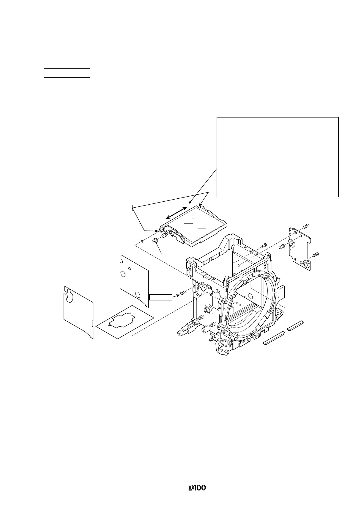
ASSEMBLY AND ADJUSTMENT
1. FRONT BODY
Mirror Holder
B2231
#721
#233
#238
#240
#239
#199
#199
#236
#22
#190
#189
B237
#633x2
① Afx both ocked paper and mirror receipt mold on the
front body #22.
(Extrusion from each side of #22 is not allowed).
② Press the shaft #199 A side into the front body #22 and
press 1/3 of the shaft #199 B side into the front body #22.
③ Place the washer #721 through the shaft #199 A side.
④ Assemble the mirror holder B2231 in the front body
#22 aligning it with the shaft #199 A side and press the
shaft #199 B side in the body to the end, aligning it with
the mirror holder B2231.
After the mirror holder is assembled in the
front body #22 in step ④ above, check
the thrust backlash. If the backlash is out
of standard, replace it by either of three
thickness types of the washer #721 and adjust
it.
Backlash Standard: 0.02 mm or less (0 is not
allowed)
⑤ Stand the mirror up and assemble the sub-mirror
deection pin #236 into the front body #22.
⑥ Align the hole on the mirror box PCB B237 with the
boss on the front body #22, and assemble and x them
using the screws #633×2.
After putting #199
into #22
C-8008B
To both holes for
#199
LEN317F

 Loading...