Chapter 5 Laser Unit
5.1 Overview of the Laser Units
1-98
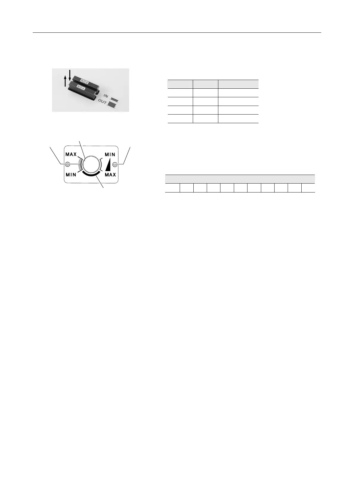
Figure 5.1-2
(1) ND filter slider (C-LU2, C-LU3)
Table 5.1-3
ND4 ND8 Brightness
OUT OUT 1
IN OUT 1/4
OUT IN 1/8
IN IN 1/32
IN: In optical path
OUT: Not in optical path
Figure 5.1-3
(2) Light control knob (C-LU3EX only)
You can control the light intensity of each laser in 11 steps
or on a continuous basis.
The table below shows the guideline of transmittance for
the Ar laser on a continuous basis control.
Table 5.1-4
In the unavailable range in the right figure, the laser beam
is not emitted.
Transmittance (%)
100 80 50 25 10 3.5 1.3 0.5 0.15 0.05 0.02
(3) Ar wavelength selector (Optional for C-LU3EX)
The wavelength of the Ar laser is switchable (488 nm or
514 nm).
(4) Single mode fiber lead-in section
This is provided to connect to a single mode fiber.
(5) TI-LUSU shutter unit connector
This connector is provided to connect the cable for the
TI-LUSU shutter unit.
(6) AOM connector
This connector is to connect the AOM controller
(7) Power switch
This is the main power switch of the LU4A four-laser
module A.
When this switch is pressed, power is supplied to the
primary source only. Power supply to the secondary
source is subject to the state of the remote switch (9).
(8) AC inlet
(9) Remote switch
This is the remote power switch of the LU4A four-laser
module A.
When this switch is pressed, power is supplied to the
secondary source in conjunction with the power supply to
the PC. (Always remain the power switch (1) on.) When
this switch is off, power is supplied to the secondary
source when the power switch (1) is pressed,
independently of the power supply to the PC.
(10) CONTROLLER connector
This connector is used to control the shutter of the LU4A
four-laser module A. (Do not use in this system.)
IN: Push in
OUT: Pull out
Step
control range
Continuous
control range
Mark on the knob
Unavailable range