Chapter 5 Laser Unit
5.3 C-LU3EX Three-laser Unit EX
1-140
2
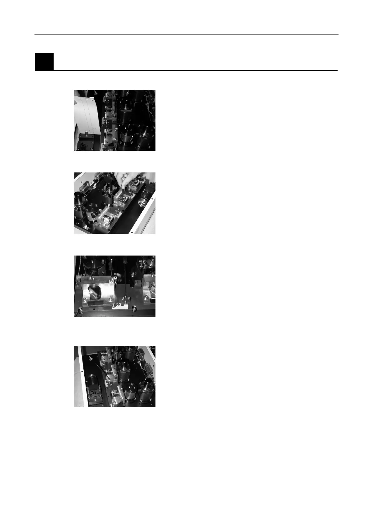
Adjusting the Ar dichroic mirror adjustment unit angle
(The dichroic mirror adjustment unit adjusts the laser angle.)
Figure 5.3-40
1. Place the dichroic mirror centering tool (for the EX) in
front of the fiber coupling.
Figure 5.3-41
2. Loosen the two horizontal rotation clamp screws of
the Ar dichroic mirror adjustment unit.
Figure 5.3-42
3. Adjust the horizontal axis setscrews and align the
horizontal axis of the laser light with the tool opening
position.
If the AOM is attached, first turn off the AOM
controller and check the zero-order light position.
Always check that the first-order (strong) light is
aligned with the hole in the tool. Check that the
first-order light is used for subsequent adjustments.
Check that the first-order light is used for subsequent
adjustments.
Figure 5.3-43
4. Loosen the Ar dichroic mirror adjustment unit vertical
clamp screw.
The L1 and L3 clamp screws are spring plungers.
(On products manufactured after May 2004)
Unscrew the screws by approximately 90° from the
fully-tightened position to tension the spring.