Chapter 5 Laser Unit
5.3 C-LU3EX Three-laser Unit EX
1-145
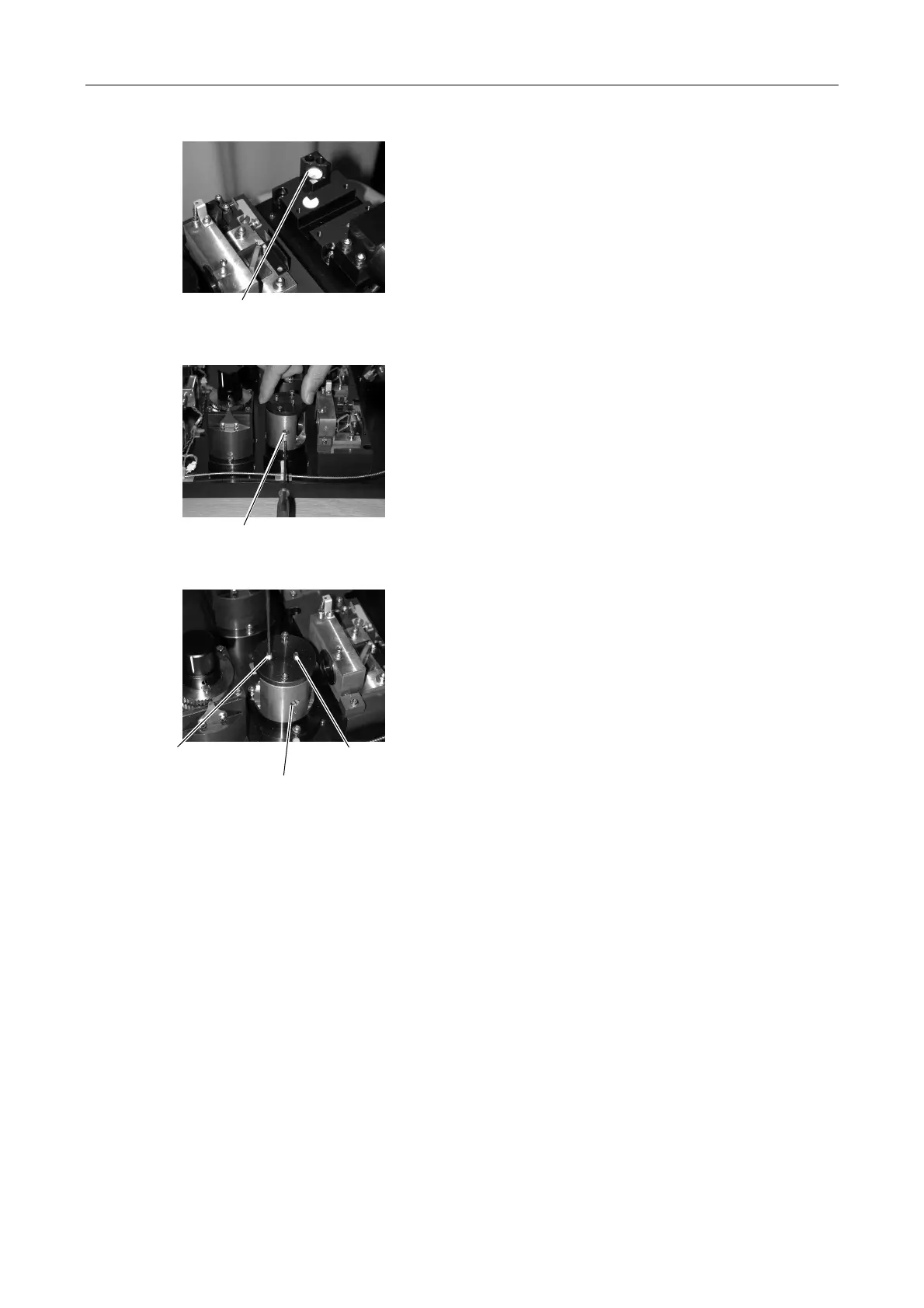
Figure 5.3-53
Figure 5.3-54
Figure 5.3-55
2. Adjust the beam shift unit to align the positions of the
other laser beams with the position of the Ar laser
beam scattered by the mirror reflector in front of the
fiber coupling.
Adjust horizontally either by rotating the beam shift
unit by hand or by inserting an Allen wrench in the
side and turning the horizontal axis setscrew.
Adjust vertically by moving the vertical axis setscrew
up or down with the clamp screw loosened.
3. Repeat steps 1. and 2. to make the light from the
three lasers coincide with the Ar laser beam position
on the mirror reflecting surface and the target
position at a distance of 50 cm.
(Take enough time to perform this step thoroughly.
Getting the laser beams to coincide here will make it
easier to adjust transmission into the optical fiber.)
Horizontal axis setscrew
Mirror reflector
Vertical axis setscrew
(farther from axis A)
Vertical axis clamp
screw
xis A