Chapter 5 Laser Unit
5.4 LU4A Four-laser Module A
1-175
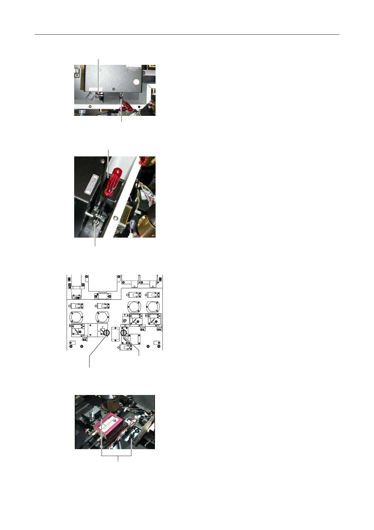
Figure 5.4-51
7. Fully loosen the clamp screw at the right of the Ar
laser mirror adjustment part viewed from the laser
coupling mirror part to the laser body. And loosen the
clamp screw to the halfway point at the left of the Ar
laser mirror adjustment part.
Figure 5.4-52
8. Insert a screw driver into the adjustment hole on the
Ar laser mirror adjustment part. And pry it to adjust
the laser light position in the vertical direction. Aim
the laser light at the hole of the centering tool
attached in step 3 by moving the screwdriver.
Figure 5.4-53
Figure 5.4-54
9.
ttach another centering tool onto the collimation pin
to the left of the AOTF unit viewed from the front of
the four-laser module A. Rotate the centering tool so
that the laser light enters the hole of the centering
tool at a right angle.
(The centering tool attached in step 3 must be
untouched. Two centering tools are used on the
laser unit to adjust the laser position.)
Tighten securely
Tighten temporarily
Adjustment hole
Ar mirror adjustment part
Centering tool attached in step 3
Centering tool attached in step 9
Centering tool