Chapter 5 Laser Unit
5.4 LU4A Four-laser Module A
1-176
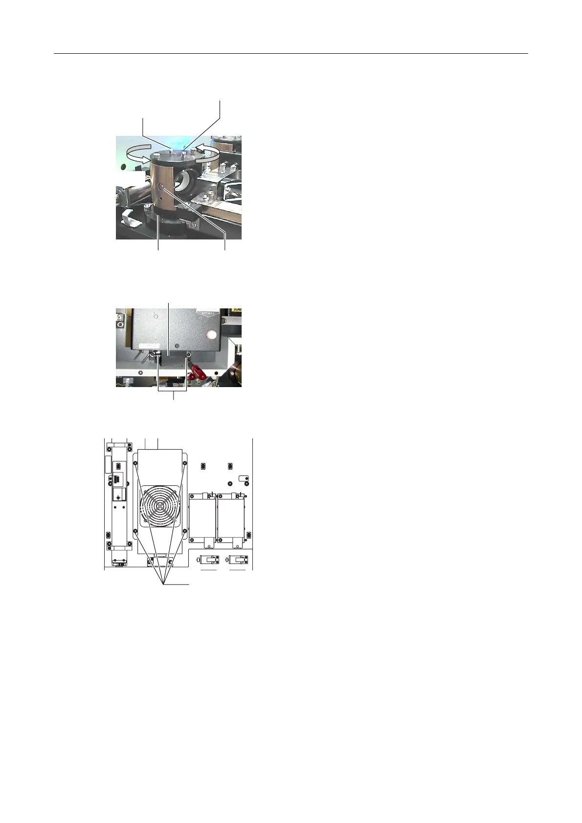
Figure 5.4-55
10. Loosen the clamp screw for the horizontal direction
of the L3 beam shift part.
11. The laser light direction can be adjusted horizontally
by rotating the whole L3 beam shift part by hands.
Aim the laser light at the hole of the centering tool
attached in step 9 by rotating the L3 beam shift part.
12. Loosen the clamp screw for the vertical direction of
the L3 beam shift part.
13. The laser light direction can be adjusted vertically by
rotating the setscrew for the vertical direction of the
L3 beam shift part. Aim the laser light at the hole of
the centering tool of step 9 by rotating the setscrew
for the vertical direction.
14. Repeat steps 6, 8, 11, and 13. The laser light must
pass through the holes of the centering tools.
Figure 5.4-56
Figure 5.4-57
15. After the completion of the adjustment, tighten two
clamp screws of the Ar laser mirror adjustment part
to fix the Ar laser mirror adjustment part. And then,
fix the Ar laser body with four hexagonal bolts.
Rotate by hand
Vertical clamp screw
(nearer to the axis A)
Vertical setscrew
(farther from the axis A)
Axis A Horizontal clamp screw
Clamp screw (2 locations)
Ar mirror adjustment part
Hexagonal bolt
(4 locations)