Chapter 5 Laser Unit
5.4 LU4A Four-laser Module A
1-178
4
Adjusting other lasers
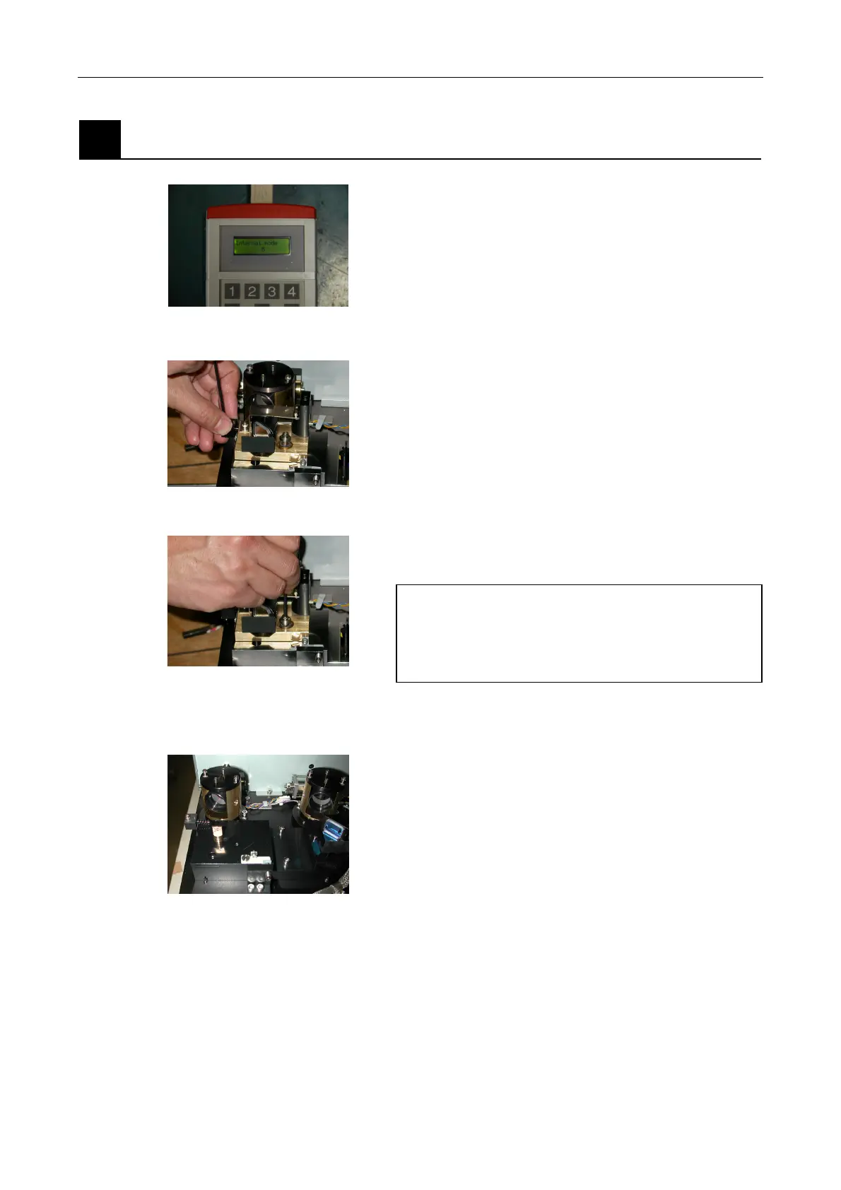
Figure 5.4-59
1. To adjust the green HeNe laser or the 561-nm
solid-state laser, select the laser wavelength with the
numeric key on the AOTF remote controller.
* To adjust the green HeNe laser,
select L5 (543 nm).
* To adjust the 561-nm solid-state laser,
Select L6 (561 nm).
(At the initial condition settings, the AOTF driver is
not adjusted well enough. Therefore the transmitted
light from the AOTF may be dark.)
Figure 5.4-60
2. Loosen the clamp screw of the spring of the L4
dichroic mirror adjustment part. And then, detach the
spring.
3. Loosen the clamp screw of the L4 dichroic mirror
adjustment part body. And then, detach the dichroic
mirror adjustment part body.
Precautions
At the detachment of the dichroic mirror
adjustment part, the collimation pin may come with
the dichroic mirror adjustment part body. Be
careful to prevent the pin from getting lost.
Figure 5.4-61
To complete the adjustment, follow the procedures described below under each module name.
Figure 5.4-62
< for LU4A >
4. For the green HeNe or 561-nm solid-state laser,
attach the centering tool to the collimation pin after
detaching the dichroic mirror adjustment part. Rotate
the centering tool so that the laser light enters the
hole of the centering tool at a right angle. Adjust the
beam shift part so that the laser light enters the hole
L.