Chapter 5 Laser Unit
5.4 LU4A Four-laser Module A
1-179
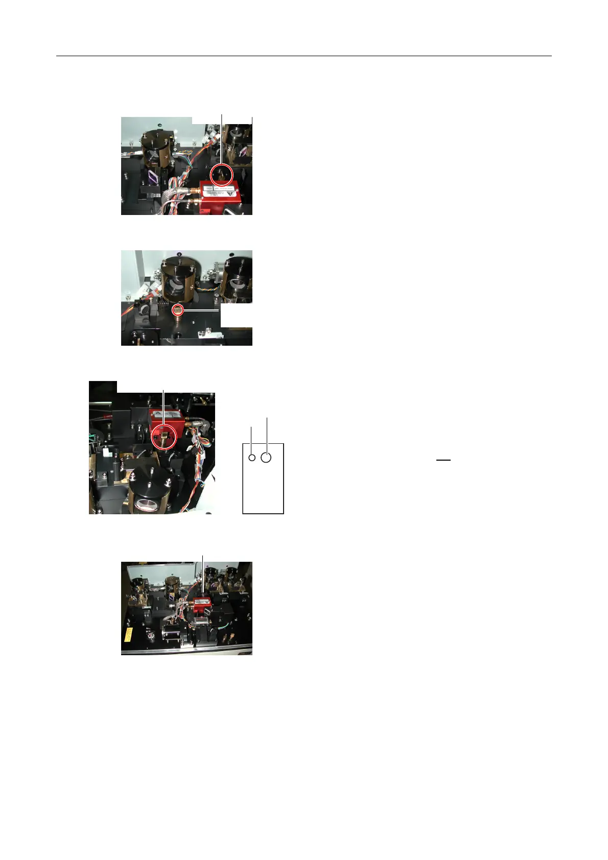
Figure 5.4-63
5. Reattach the dichroic mirror adjustment part and
attach the centering tool to position B. Adjust the
dichroic mirror adjustment part in both horizontal and
vertical directions so that the laser light enters the
hole L.
Figure 5.4-64
6. As for the 405 (440) LD and 638LD, do the same as
in the case of L4. Namely, attach the centering tool
to the collimation pin after detaching the dichroic
mirror adjustment part. Adjust the beam shift part so
that the laser light enters the hole L.
Figure 5.4-65
7. Reattach the dichroic mirror adjustment part and
attach the centering tool to position B. Adjust the
dichroic mirror adjustment part in both horizontal and
vertical directions so that the laser light enters the
hole S (located at a distance of 1 mm left to the hole
L with respect to the AOTF unit viewed from the front
of the four-laser module A), not
the hole L.
Figure 5.4-66
8. After adjustment, reattach the laser coupling mirror
part.
9. Select Line 3 (L3) on the AOTF remote controller
and change the Ar laser wavelength to 488 nm.
Position B
Centering tool
Hole L
Centering tool
Hole L
Position B Centering tool Hole S
Hole S
Hole L
Laser coupling mirror part