Chapter 5 Laser Unit
5.4 LU4A Four-laser Module A
1-181
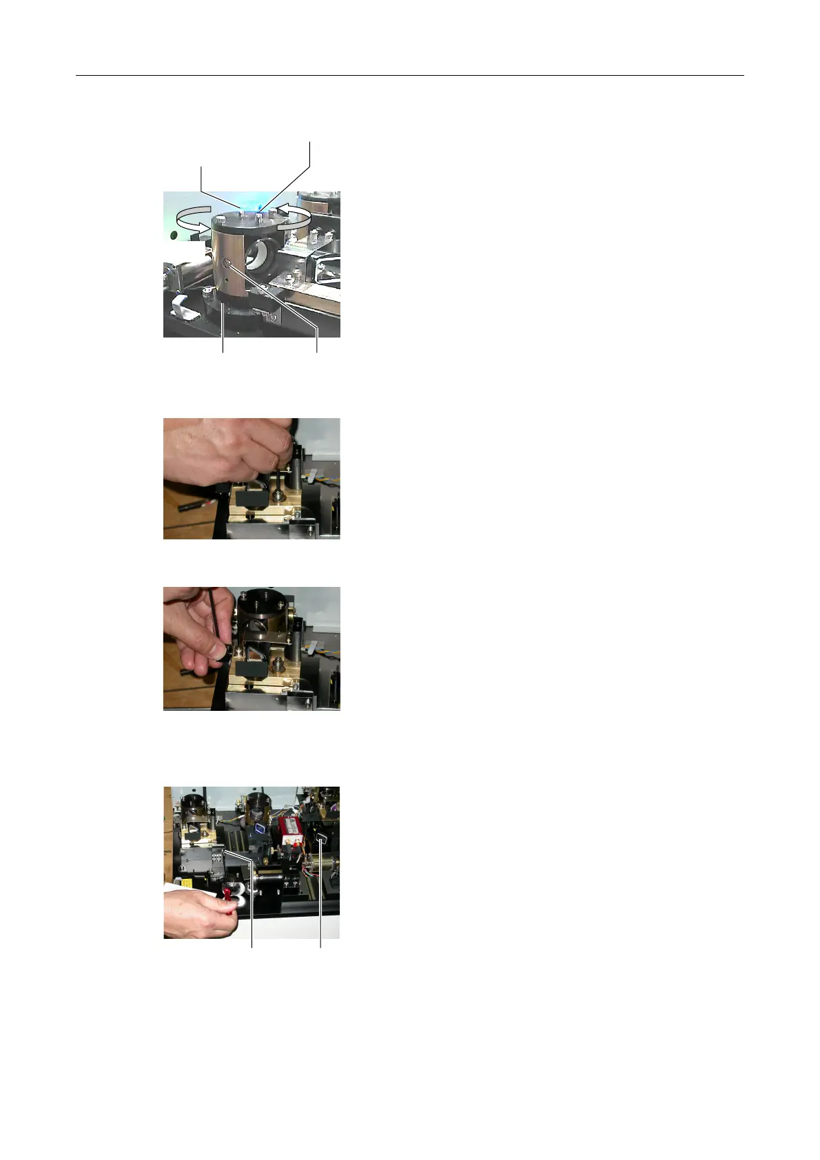
Figure 5.4-70
7. Loosen the clamp screw for the horizontal direction
of the L4 beam shift part.
8. Aim the laser light at the hole of the centering tool
attached in step 4 by rotating the L4 beam shift part.
9. Loosen the clamp screw for the vertical direction of
the L4 beam shift part.
10. Aim the laser light at the hole of the centering tool
attached in step 4 by rotating the setscrew for the
vertical direction of the L4 beam shift part.
11. Close the L4 laser shutter. And then remove the
centering tool attached in step 4.
Figure 5.4-71
12. Restore the dichroic mirror adjustment part to its
original position. (See step 3.) And then fix it with a
clamp screw temporarily.
Figure 5.4-72
13. Attach the spring of the dichroic mirror adjustment
part.
14. Manually open the L4 laser shutter.
Figure 5.4-73
15. Aim the laser light at the hole of the centering tool
attached in step 3 in "3. Adjusting the Ar laser
position" by rotating the setscrew for the horizontal
direction adjustment of the L4 dichroic mirror
adjustment part.
Rotate by hand
Vertical clamp screw
(nearer to the axis A)
Vertical setscrew
(farther from the axis A)
Axis A Horizontal clamp screw
Horizontal-direction setscrew
Centering tool