Chapter 5 Laser Unit
5.4 LU4A Four-laser Module A
1-187
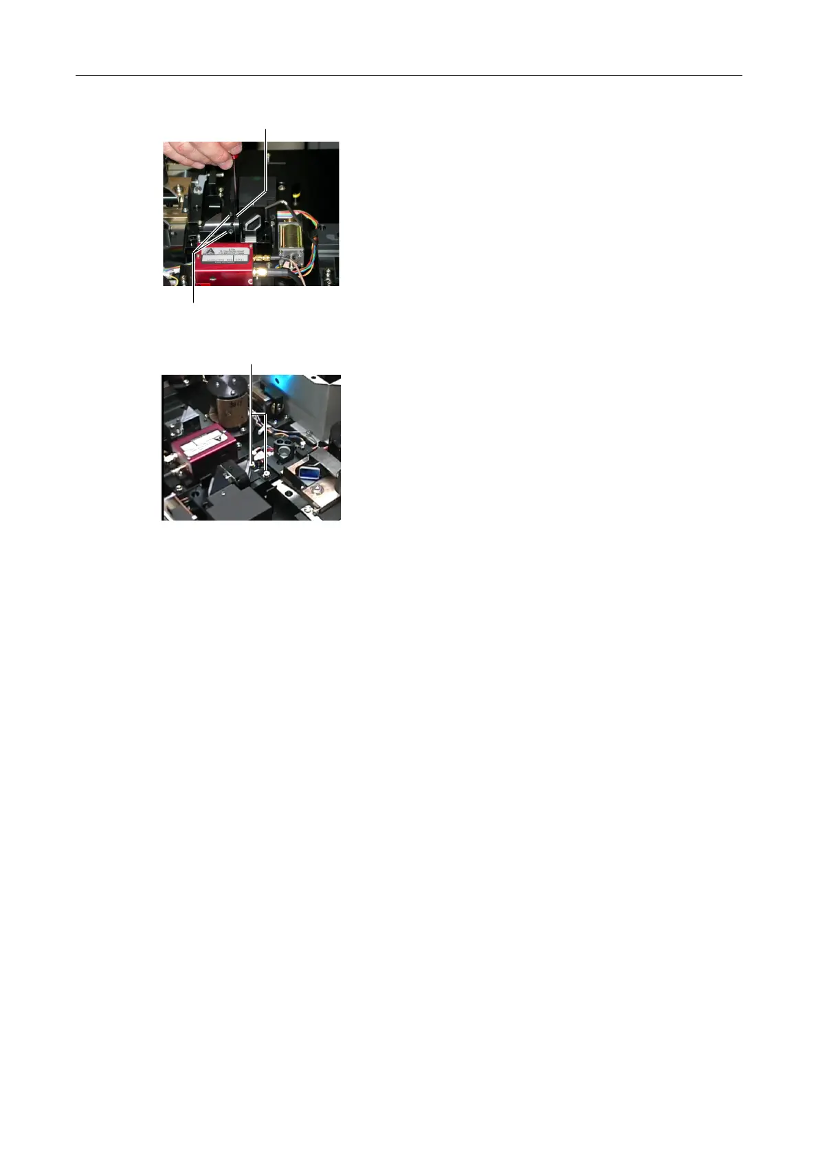
Figure 5.4-86
6. Slightly loosen the two clamp screws for the vertical
direction adjustment on the laser coupling mirror
part.
7. Insert a screwdriver into the adjustment hole for the
vertical direction adjustment on the laser coupling
mirror part. And pry it to adjust the laser light position
in the vertical direction.
Aim the laser light at the hole of the centering tool
attached in step 2 by moving the screwdriver.
Figure 5.4-87
8. Tighten two hexagonal bolts on the laser coupling
mirror part and two clamp screws of step 6 after
adjustments.
9. Close the L3 laser shutter and the laser shutter at
the incident side of the mirror part.
Clamp screw
Vertical adjustment hole
Hexagonal bolts