Chapter 5 Laser Unit
5.4 LU4A Four-laser Module A
1-186
2
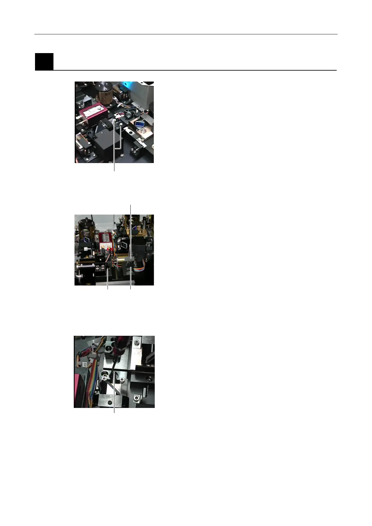
Adjusting the laser coupling mirror part
Figure 5.4-83
Adjust the optical path of the Ar laser (488 nm). The
optical path of the Ar laser is used as a reference. Optical
paths of other lasers are aligned with it.
1. Restore the laser coupling mirror part to its original
position. (Refer to Step 2 in "3. Adjusting the Ar laser
position" in Section 5.4.3, “Laser Rough Adjustment
1.”)
Figure 5.4-84
2. Attach the centering tool into the optical path at the
inlet of the optical fiber. Rotate the centering tool so
that the laser light enters the hole of the centering
tool at a right angle.
3. Manually open the L3 laser shutter. (The laser
shutter at the incident side of the mirror part must be
opened manually too.)
4. Select the line three (L3) with the AOTF remote
controller to use the 488-nm Ar laser.
Figure 5.4-85
5. Insert a screwdriver into the adjustment hole for the
horizontal direction adjustment on the laser coupling
mirror part. And pry it to adjust the laser light position
in the horizontal direction.
Aim the laser light at the hole of the centering tool
attached in step 2 by moving the screwdriver.
Tighten temporarily
Laser shutter at the incident side of the mirror part
Centering tool Mirror reflector
Horizontal adjustment hole