Chapter 1 System Configurations and Part Names
1.4 Name of Each Part
1-60
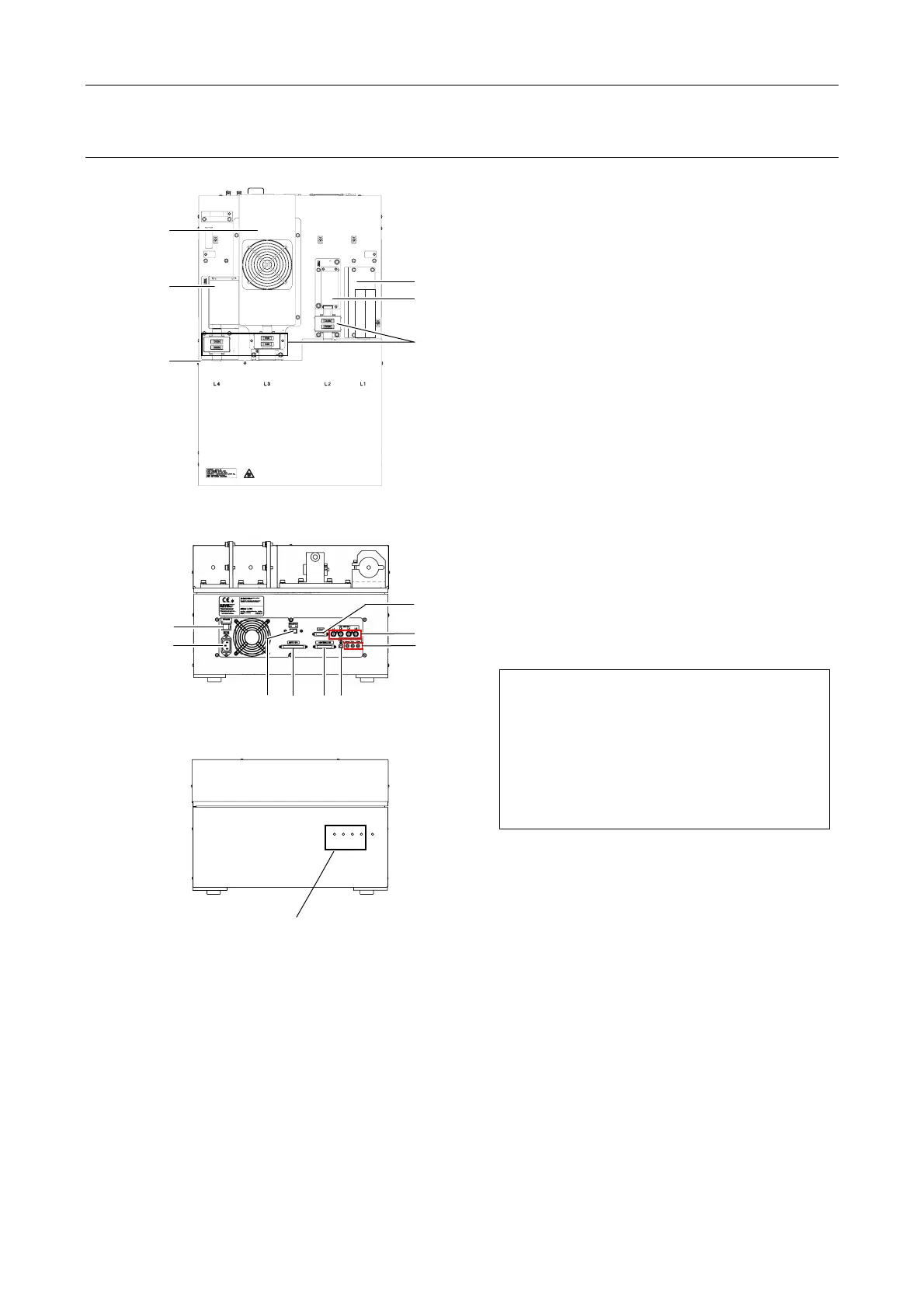
Four-laser module A (LU4A)
Fix the laser unit with
four blocks during
transportation.
Figure 1.4-45
Figure 1.4-46
L4
L3
L2
L1
POWER
Figure 1.4-47
(1) Laser mounting position L1
(2) Laser mounting position L2
(3) Laser mounting position L3
(4) Laser mounting position L4
(5) Single-mode fiber
(6)
*1
ND filter sliders
(7) Power switch
(8) AC inlet
(9) Remote switch
(10) CONTROLLER connector
(Do not use in this system.)
(11) AOTF/PC connector
(Do not use in this system.)
(12) Interlock cable connectors
(13) LUSU connector
(14) USB connector
(15) LD connector
(Do not use in this system.)
*1: Installed only when the N-STORM kit is
mounted
Precautions when handling the laser unit
• The laser head and the optical fiber are
precisely aligned in these units.
Avoid subjecting the laser head or optical
fiber to vibration or shock. Contact the
distributor if you need to remove the laser
head from the unit due to laser malfunction
or other reasons.
* For details of available lasers for each position of laser units, see Section 8.1.4, “Mountable Lasers” in
Chapter 8, “Specifications and Performance.”
Indicating shutter conditions
(7)
(13)
(9) (14)
(15)
(8)
(12)
(10)
(11)
(3)
(5)
(1)
(4)
(2)
(6)
1