Page 50/55 68_Afficheur_Multidisplay_um_UK_11
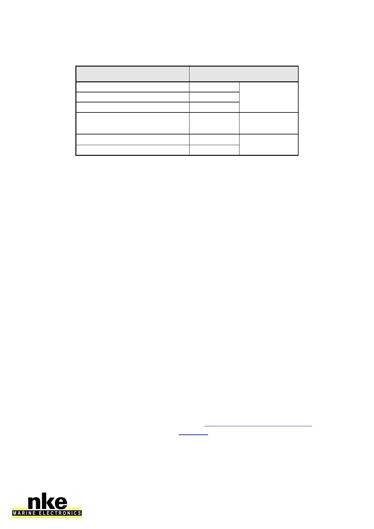
Cable colour code
white
+12V
TOPLINE Bus
black
Data Topline
braid
commun
red INIT adress
Isolate after
taken address
yellow
NMEA +
NMEA input
green
NMEA –
3.7 NODE ADRESS FOR THE MULTIDISPLAY
At the first power on, you must give a node address to the Multidisplay to enable it
to work on the system’s bus.
The default address is 0.
During the address taking, connect the red wire on the INIT terminal and start the
installation. A message is displayed and indicates to unplug the red wire and then to
plug it again. The Multidisplay will automatically take a place into the TOPLINE bus
instruments’ list of your installation:
- Either as “Master” with node 1 if this address is available on the bus,
- Either as “slave” with node 2 to 20 if node 1 is already taken by an existing
“master”.
To follow the address taking procedure of your Multidisplay, see Chapter 2.5
To follow the address resetting procedure of your Multidisplay, see Chapter 2.5
3.8 CONNECTING TO A NMEA SOURCE AND CONFIGURATION
The Multidisplay features an interface which converts NMEA sentences to the
Topline protocol. This allows the system to display the data coming from a NMEA
source on the nke displays.
Connect the NMEA device to the NMEA- and NMEA+ terminals of the 90-60-417
junction box. Be careful to respect the polarity (refer to the connection drawing). The
configuration is described in the section 2.7.5.2.2 of this manual.