Revision 6
9.
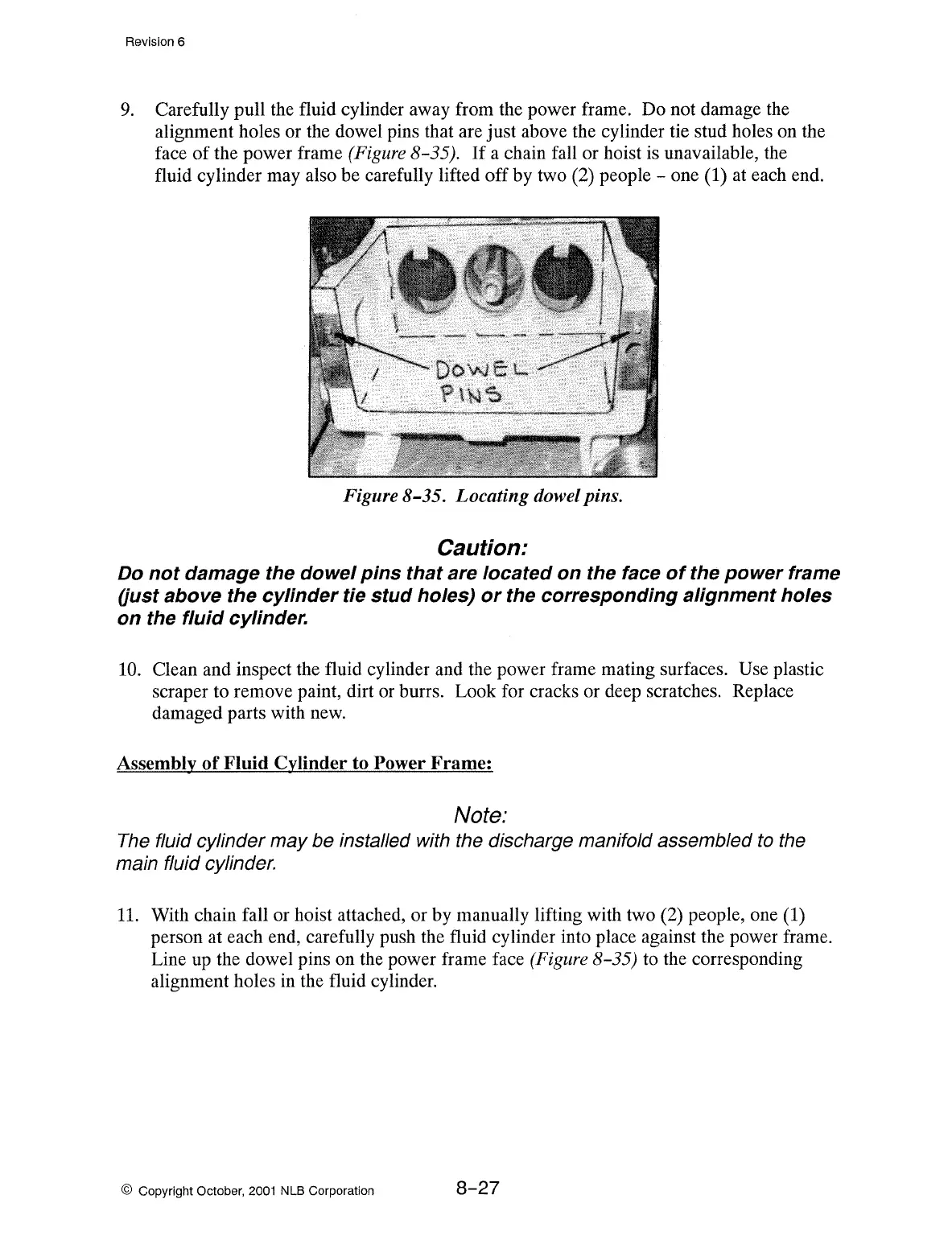
Carefully pull the fluid cylinder away from the power frame. Do not damage the
alignment holes or the dowel pins that are just above the cylinder tie stud holes on the
face
of
the power frame (Figure 8-35).
If
a chain fall or hoist is unavailable, the
fluid cylinder may also be carefully lifted off by two (2) people - one (1) at each end.
Figure 8-35. Locating dowel pins.
Caution:
Do
not
damage the
dowel
pins
that
are located
on
the face
of
the
power
frame
(just above the
cylinder
tie
stud
holes)
or
the
corresponding
alignment
holes
on
the
fluid
cylinder.
10.
Clean and inspect the fluid cylinder and the power frame mating surfaces. Use plastic
scraper to remove paint, dirt or burrs. Look for cracks or deep scratches. Replace
damaged parts with new.
Assembly
of
Fluid Cylinder to Power
Frame:
Note:
The fluid cylinder may be installed with the discharge manifold assembled to the
main fluid cylinder.
11.
With chain fall or hoist attached, or by manually lifting with two (2) people, one (1)
person at each end, carefully push the fluid cylinder into place against the power frame.
Line
up
the dowel pins on the power frame face (Figure 8-35) to the corresponding
alignment holes in the fluid cylinder.
© Copyright October,
2001
NLB Corporation
8-27