Revision 6
9.
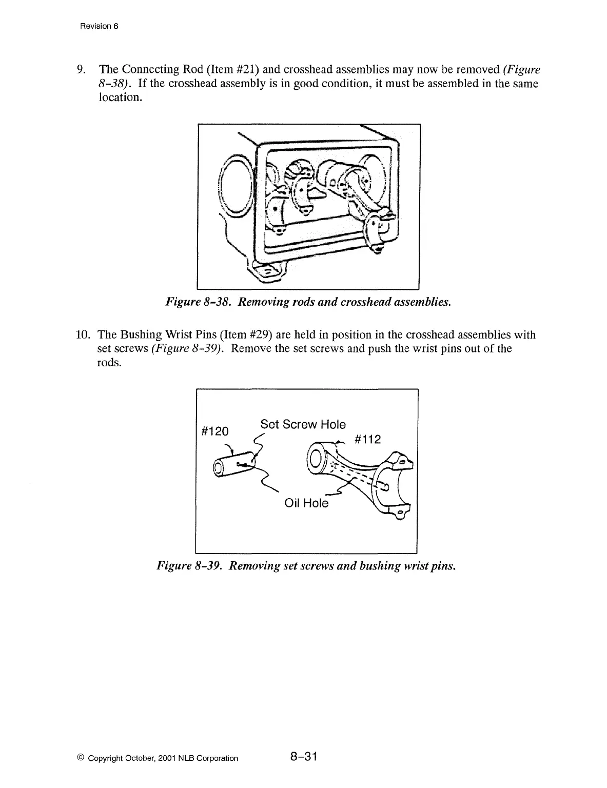
The Connecting Rod (Item #21) and crosshead assemblies may now be removed (Figure
8-38).
If
the crosshead assembly is
in
good condition, it must be assembled in the same
location.
Figure 8-38. Removing rods
and
crosshead assemblies.
10. The Bushing Wrist Pins (Item #29) are held in position in the crosshead assemblies with
set screws (Figure 8-39). Remove the set screws and push the wrist pins out
of
the
rods.
Figure 8-39. Removing set screws
and
bushing wrist pins.
© Copyright October,
2001
NLB Corporation
8-31