Issue 2 06/2005 COMPANY CONFIDENTIAL 23
Copyright © 2005 Nokia. All Rights Reserved.
RH-53/54
Nokia Customer Care
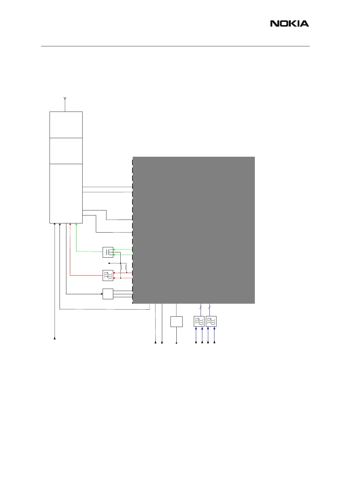
order to control the TX level a sample of the signal is taken in the FEM and used in the power
loop amplfier in Mjoelner to establish the right output power. The selection of which amplifier
chain in the FEM to be active is controlled through the 4 controllines VC1, VC2, BS and Vtx.
Figure 15:Transmitter signal path
■ PLL
The PLL supplies Local Oscillator (LO) signals for the RX and TX-mixers. In order to be able
to generate LO-frequencies for the required EGSM and PCN channels a regular synthesizer-
circuit is used. All blocks for the PLL except for the VCO, reference X-tal and loopfilter is located
in the Mjoelner IC, N600.
The reference frequency is generated by a 26MHz Voltage Controlled X-tal Oscillator (VCXO)
located in the Mjoelner IC. Only the X-tal is external. 26MHz is supplied to BB where a divide-
by-2 circuit (located in the UPP IC) generates the BB-clock at 13MHz. The reference frequency
OUTHP
OUTHM
OUTLP
OUTLM
DET
VB_DET
VANTL
TXC
TXP
Mjølner
VTXLOL
TXIP/TXIM
TXQP/TXQM
2
2
PLFB1
PLFB2
VPCTRL_G
VTX
TXC
TXP
VDDTX
Supply
filter
VR2
VTXBH
VTXBL
VANTM
VTXLOH
VBATTRF
PCN/PCS
GSM
PW-loop
filter
SAW
VTX
Balun
1/2
1/4
1/2
1/4
Open collector
Open collector
PWC
RF Controls
RF Controls
2
2
2
2
VDDDIG
VDDRXBB
VANTH
Diplexer
RX/TX switch
PA and detector
Ant
VC1 (TX/RX GSM)
VC2 (TX/RX DCS)
Band sel
VTX
PCN/PCS
Vapc
Vsense
ASIC
 Loading...