Issue 2 06/2005 COMPANY CONFIDENTIAL 55
Copyright © 2005 Nokia. All Rights Reserved.
RH-53/54
Nokia Customer Care
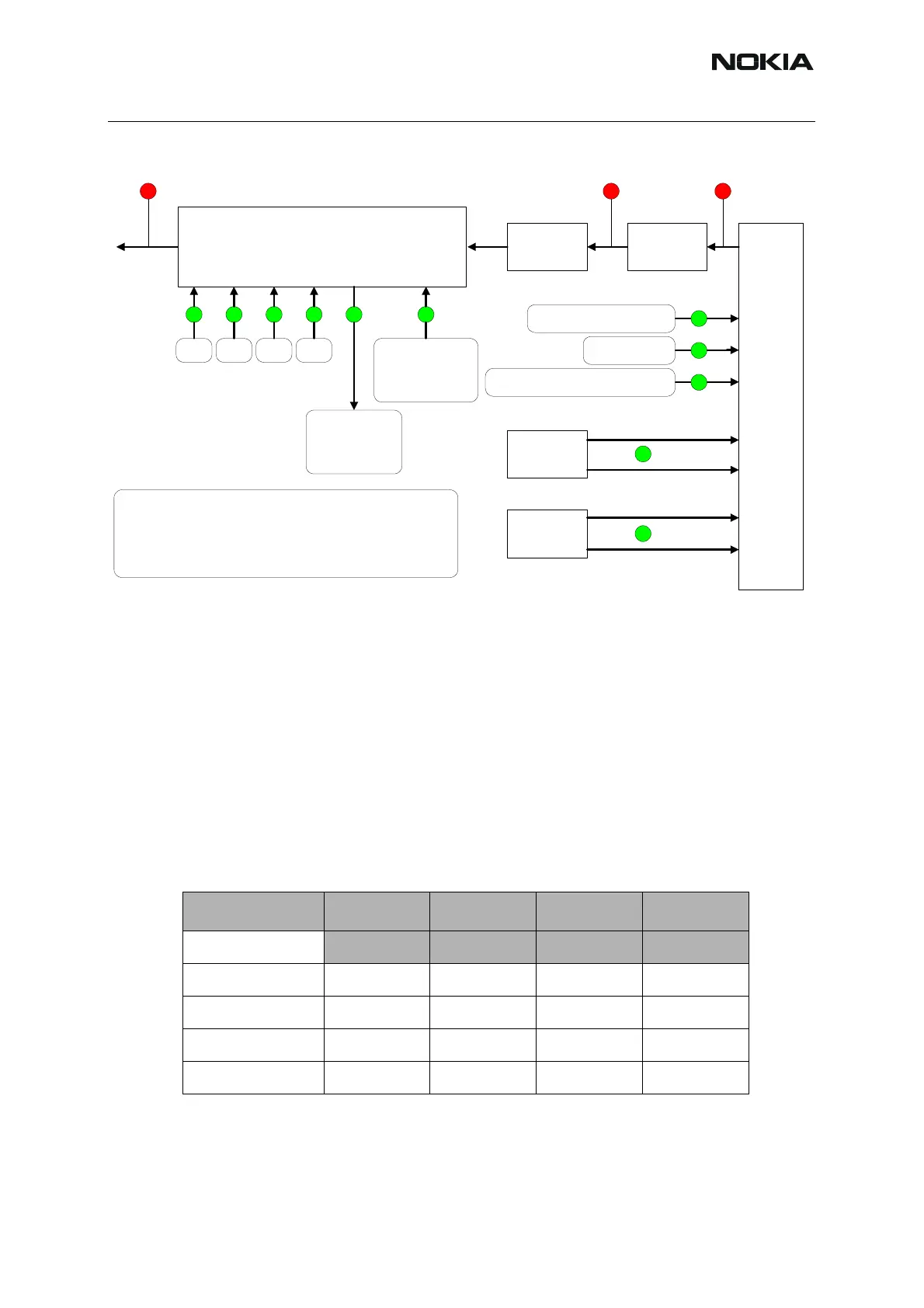
Figure 45:Signals
Logic signals for the Front End Module
Depending on the vendor of the Front End Module (FEM), different timing of the control signals
are at present:the SW supports both FEMS. R629 tells the SW which FEM control should be
active. Renesas FEM control is used when R629 is 18K and RFMD FEM control is used when
R629 is 82K.
If the FEM is exchanged with an other type, the R629 has to be changed, too.
Renesa FEM logic
Table 13: Renesa FEM logic
Mode Vtx BS VC1 VC2
VTX_B_P VTX_B_P Vant1 Vant2
Low Band RX 0 0 0 0
Low Band TX 1 0 1 0
High Band RX 0 1 0 0
High Band TX 1 1 0 1
Mjoelner
N600
Attenuator
R714
(R711)
Z603
(T600)
R611
R610
TXC (R620) Max PW 1.6V
Min PW 0.6 V
TXP (C646) 2.7V
Opamp (C644) Max PW 1.2 V
Min PW 0.65
32.5 dBm
(29.5 dBm)
+ 2 dBm + 4 dBm
FEM
N700
VC1 VC2 VTX BS
Det
Max PW: 1.13 vdc
Min PW: 0.22 Vdc
Vpc R712
Max PW: 1.2 Vdc
Min PW: 0.65 Vdc
Names in () is for high band
All the red signals are pulsed with the burst
The Green "DC" signals are pulsed with the burst
In local mode random burst RF signals can be demodulated by a GSM
tester
 Loading...