7210 SAS-D CHASSIS INSTALLATION GUIDE Installing the Chassis
Issue: 08 3HE 10087 AAAA TQZZA Edition 01 41
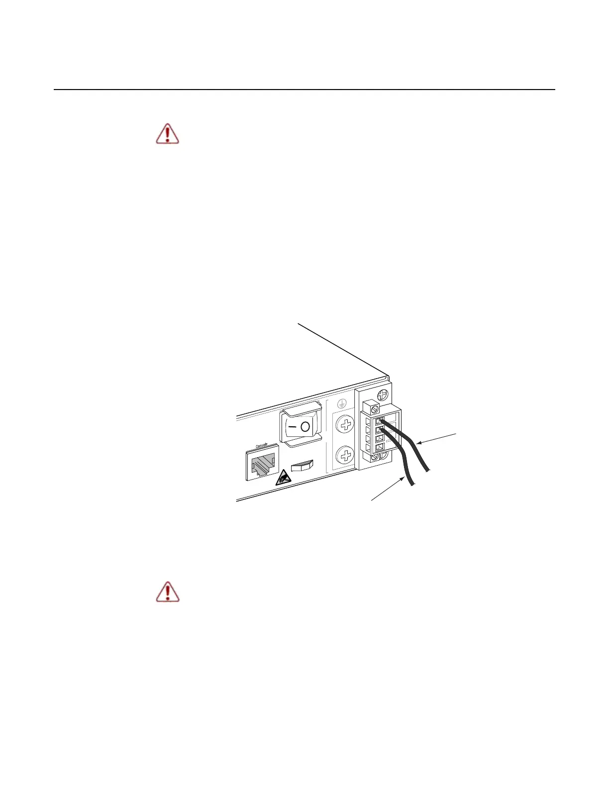
Step 3. Connect the –48 VDC power feed using the –48 VDC input and RET
(return) lines. Insert the wires into the DC input plug (using a small flat-tip
screwdriver). Color code the wiring according to local standards to ensure
that the input power and ground lines can be easily distinguished. Figure 16
shows this step in greater detail:
Figure 16 Connecting a –48 VDC Power Source
Step 4. After the power source is tuned on, set the power button on the front of the
power supply module to the ON position (marked – ).
Warning:
• The equipment under test (EUT) is specified for DC-I power configurations. The
battery returns must remain isolated until they reach the main power bus.
• In the DC-C configuration, the ampacity of the conductor connecting the
equipment frame to the BR conductor shall be equal to or greater than the
ampacity of the associated BR conductor
Warning: If the power leads are plugged into the wrong holes, the power supply will
not work properly and may damage the switch.
7210SASdc_0015
-48V (Pin 1)
Return (Pin 2)

 Loading...