Installing the Chassis
42
7210 SAS-D CHASSIS INSTALLATION GUIDE
3HE 10087 AAAA TQZZA Edition 01 Issue: 08
Step 5. Check the power LED as the switch is powered on to verify that the LED
indicating external power status is on, and that the LED indicating internal
power conversion is on. If not, recheck the power source and power cable
connections at the supply source and at power supply module.
3.2.5.2.2 Connecting to a +24 VDC Power Source
To connect the switch to a +24 VDC power source:
Step 1. Before a +24 VDC power supply module can be used, you must connect an
external DC power source to the DC power connection on the right side of
the front panel.
To provide adequate circuit protection between the DC power source and
the switch, all intermediate wiring and circuitry should be rated to carry a
load at least two times the maximum rating for this switch (see section 7).
The wiring between the DC power supply and the switch must be stranded
copper wire within the range of 10 to 24 AWG.
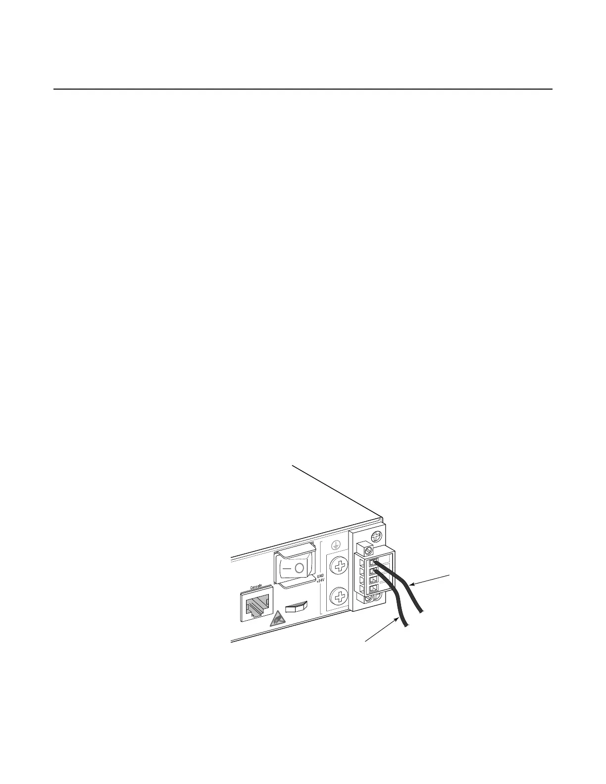
Step 2. Connect the +24 VDC power feed using the GND (ground) and +24 VDC
input lines. Insert the wires into the DC input plug (using a small flat-tip
screwdriver). Color code the wiring according to local standards to ensure
that the input power and ground lines can be easily distinguished. Figure 17
shows this step in greater detail:
Figure 17 Connecting a +24 VDC Power Source
7210SASdc_0014
Ground (Pin 1)
+24V (Pin 2)

 Loading...