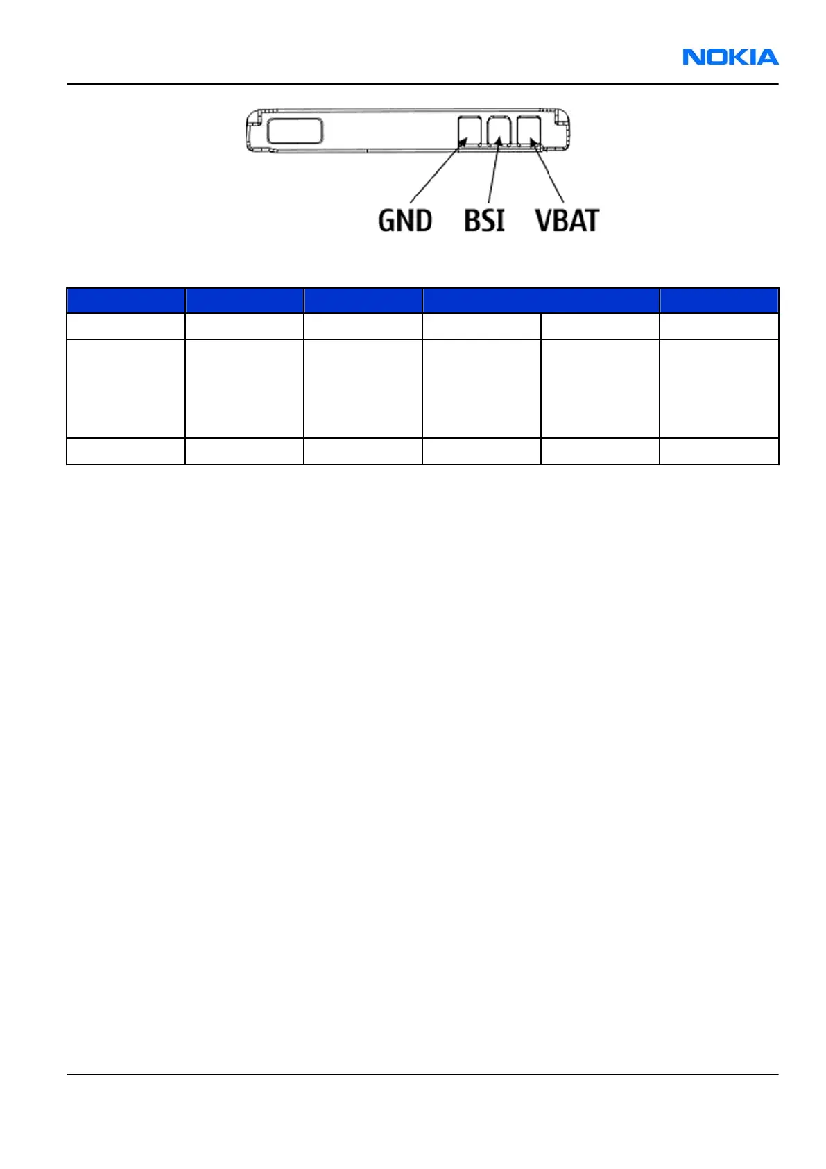
Figure 56 Battery pin order
Table 14 Battery interface connections
Pin Signal I/O Engine connection Notes
1 VBAT -> EM ASIC N2200 VBAT Battery voltage
2 BSI -> EM ASIC N2200 BSI Battery size
indication
(fixed resistor
inside the
battery pack)
3 GND GND Ground
Battery temperature is estimated by measuring separate battery temperature NTC via the BTEMP line, which
is located on the transceiver PWB.
For service purposes, the device SW can be forced into local mode by using pull down resistors connected to
the BSI line.
User interface
Display interface
The device supports Oxford QVGA 2.8” TFT display with 320 x 240 resolution and 24bit colors. It uses 8-bit
display interface.
Keyboard
The device uses external COP8 micro controller to handle engine & qwerty keyboard matrix. The
communication between COP8 and RAP is handled by I2C bus.
Display and keyboard backlight
The device has one LED Driver (SMPS) that is used to drive six display LEDs.
Display LEDs are connected in to two three LED series. Current adjustment of the driver is done from the
display LED branch, and keyboard current also depends on the display brightness. In a typical use case,
keyboard LEDs are turned ON only in dark ambient lighting conditions.
The keyboard backlight is made with electroluminance. The device has discrete EL-driver, which provide
backlight for keyboard.
ALS interface
Ambient Light Sensor (ALS) is located in the upper part of the phone. It consists of the following components:
• lightguide (part of the front cover)
• phototransistor (V4400) + resistor (R4401)
• NTC + resistors (R4400, R4402, R4403)
RM-88
System Module Nokia Customer Care
Issue 1 COMPANY CONFIDENTIAL Page 8 –15
Copyright © 2006 Nokia. All rights reserved.