Cabinet cabling
DN991456 © Nokia Corporation 59 (72)
Issue 3 en Nokia Proprietary and Confidential
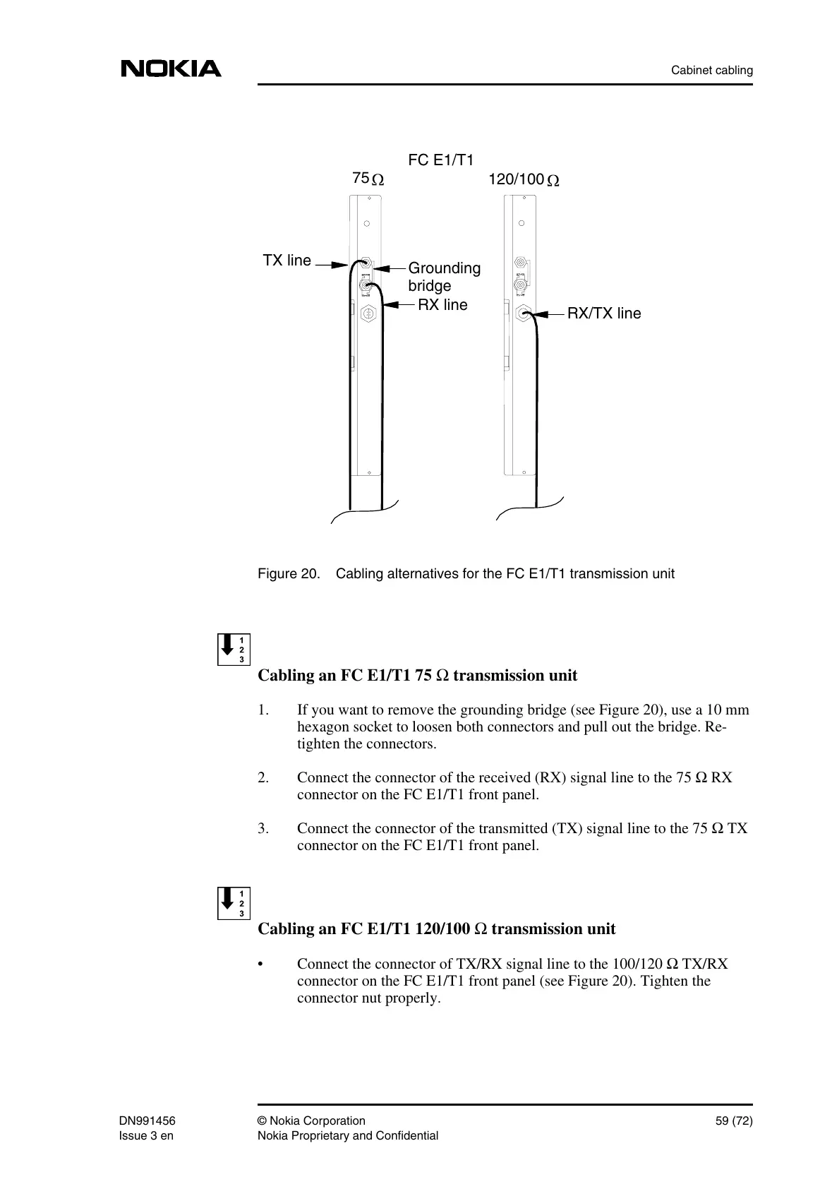
Figure 20. Cabling alternatives for the FC E1/T1 transmission unit
Cabling an FC E1/T1 75 Ω transmission unit
1. If you want to remove the grounding bridge (see Figure 20), use a 10 mm
hexagon socket to loosen both connectors and pull out the bridge. Re-
tighten the connectors.
2. Connect the connector of the received (RX) signal line to the 75 Ω RX
connector on the FC E1/T1 front panel.
3. Connect the connector of the transmitted (TX) signal line to the 75 Ω TX
connector on the FC E1/T1 front panel.
Cabling an FC E1/T1 120/100 Ω transmission unit
• Connect the connector of TX/RX signal line to the 100/120 Ω TX/RX
connector on the FC E1/T1 front panel (see Figure 20). Tighten the
connector nut properly.
RX line
TX line
RX/TX line
FC E1/T1
120/100
75
Grounding
bridge
 Loading...