Cabinet cabling
DN991456 © Nokia Corporation 61 (72)
Issue 3 en Nokia Proprietary and Confidential
Cabling an FXC E1 transmission unit
1. If you want to remove the grounding bridge (see Figure 21), use a 10 mm
hexagon socket to loosen both connectors and pull out the bridge. Re-
tighten the connectors.
2. Connect the connector of the received (RX) signal line to the 75 Ω RX
connector on IF1.
3. Connect the connector of the transmitted (TX) signal line to the 75 Ω TX
connector on IF1.
4. Cable the other IFs in the same manner (see Figure 21).
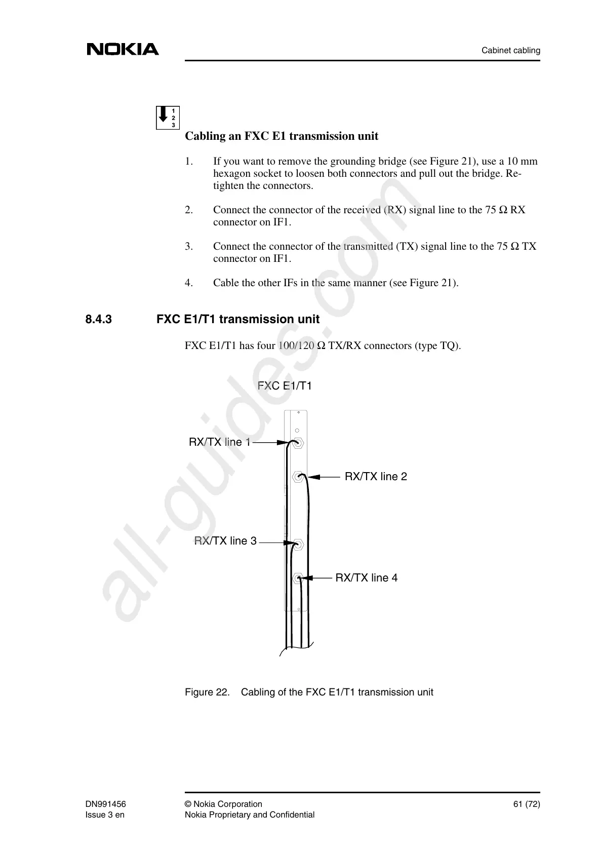
8.4.3 FXC E1/T1 transmission unit
FXC E1/T1 has four 100/120 Ω TX/RX connectors (type TQ).
Figure 22. Cabling of the FXC E1/T1 transmission unit
FXC E1/T1
RX/TX line 4
RX/TX line 3
RX/TX line 2
RX/TX line 1
 Loading...