Installation
60 (72) © Nokia Corporation DN991456
Nokia Proprietary and Confidential Issue 3 en
Note
8.4.2 FXC E1 transmission unit
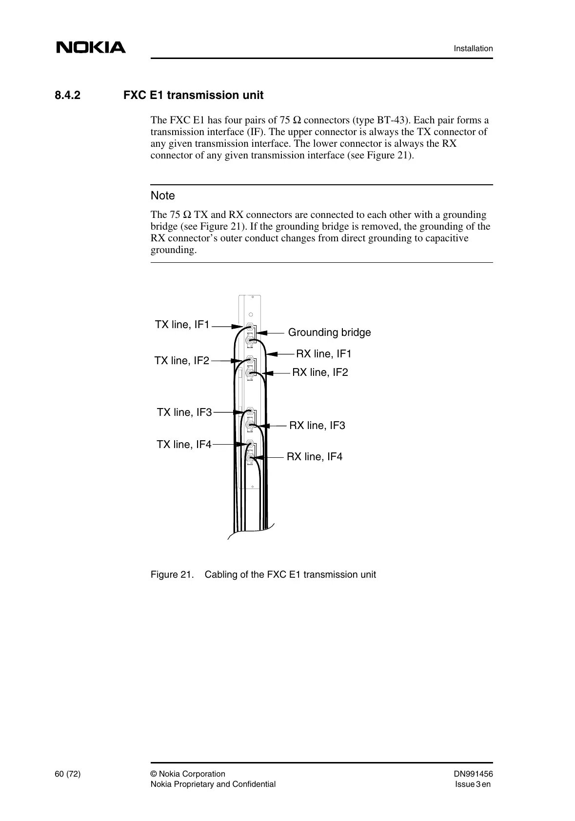
The FXC E1 has four pairs of 75 Ω connectors (type BT-43). Each pair forms a
transmission interface (IF). The upper connector is always the TX connector of
any given transmission interface. The lower connector is always the RX
connector of any given transmission interface (see Figure 21).
The 75 Ω TX and RX connectors are connected to each other with a grounding
bridge (see Figure 21). If the grounding bridge is removed, the grounding of the
RX connector’s outer conduct changes from direct grounding to capacitive
grounding.
Figure 21. Cabling of the FXC E1 transmission unit
RX line, IF4
TX line, IF4
TX line, IF3
RX line, IF3
RX line, IF2
TX line, IF2
TX line, IF1
RX line, IF1
Grounding bridge
 Loading...