Parameter Reference
Parameter Reference
138 139
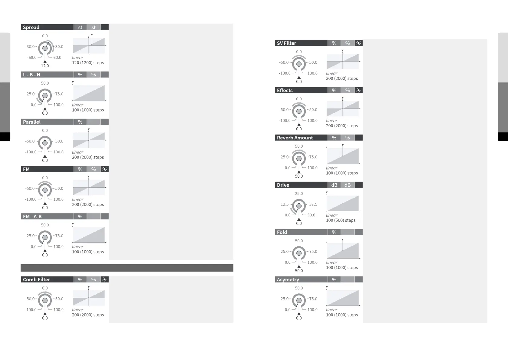
Feedback mix factor for the output of the State Variable
Filter.
Feedback mix factor for the output of the Eects chain. The
reverb amount in the feedback can be set by the “Reverb
Amount” fader independantly. Since the signal is mono-
phonic, such feedback will cause intermodulation between
the voices.
Controls the amount of reverb in the feedback indepen-
dantly from the Mix in the Reverb section.
0.0 %: dry, no reverb signal
50.0 %: mix of 50 % dry and 50 % wet signal
100.0 %: wet, 100 % reverb signal
Input gain [in dB] of the sine shaper stage. Higher gains will
create more distortion and harmonics.
Amount of folding back of the shaper curve for high input
amplitudes.
0.0 %: flat saturation, no folding
100.0 %: fully folded back (periodic sine curve)
A higher amount of folding leads to a soer but more nasal
sound.
Asymetry of the shaper curve, generating even (2nd, 4th, ...)
harmonics. At higher values, it becomes a parabolic curve
that shis the frequency of the fundamental to its double.
Feedback Mixer
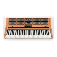
Amount of splitting of the cutos of the two 2-pole filters.
Half of the value is applied as a positive oset to the adjusted
cuto for the first stage and as a negative oset for the
second stage [in semitones].
The split reduces the strong resonance peak in the 4-pole
mode and allows filter curves with two formants. In band-
pass/bandreject mode it controls the width of the band.
Crossfades between the lowpass, bandpass and highpass
outputs of the two filter stages.
(first stage -> second stage: LP -> LP, BP -> LP, HP -> LP, HP ->
BP, HP -> HP)
At zero, the two 2-pole filter stages are in series forming a
4-pole filter. Positive values crossfade to a parallel structure
where the filter outputs are added. In bandpass mode (L-B-H
= 50.0%), the parallel structure with a negative Spread works
as a band-reject filter. Negative values also crossfade to a
parallel structure, but here the lower filter is subtracted,
which leads to phase cancellations.
Amount of modulation of the cuto frequencies by the
output signals of Oscillator & Shaper A and B, with the FM
A-B knob determining their mix. The amount is relative to the
cuto frequency.
The signal for the FM (cuto frequency modulation) of the
State Variable Filter as a crossfade between the outputs of
Oscillator & Shaper A and Oscillator & Shaper B.
Feedback mix factor for the output of the Comb Filter.
Feedback Mixer
Feedback Mixer