Gear units – Operating and Assembly Instructions
22 B 1000 en-4419
Pos: 79 /Anleitungen/Getriebe/3. Montage, Lagerung, Vorbereitung, Aufstellung/Montage/Montage von Naben auf Getriebewellen 01 - headline @ 34\mod_1559656840006_388.docx @ 2538362 @ 2 @ 1
3.6 Fitting hubs on the gear shafts
Pos: 81 /Anleitungen/Getriebe/3. Montage, Lagerung, Vorbereitung, Aufstellung/Montage/Montage von Naben auf Getriebewellen 02 @ 39\mod_1573564927604_388.docx @ 2574386 @ @ 1
The gear unit may be damaged by axial forces.
• Do not allow any harmful axial forces to act on the gear unit. Do not strike the hub with a hammer.
During assembly, take care that the shaft axes are precisely aligned with each other and comply with
the manufacturer’s tolerance specifications. Drive and driven elements, e.g. coupling and chain-wheel
hubs must be mounted onto the drive and driven shaft of the gear unit using suitable pullers that will
not apply damaging axial forces to the gear unit. In particular, do not hit the hubs with a hammer.
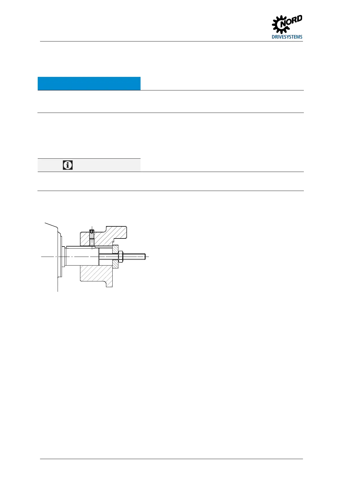
Use the end thread of the shafts for pulling. Fitting can be facilitated by coating the hub with lubricant
or heating it up to approx. 100 °C beforehand.
The coupling must be positioned according to the installation instructions (specific drawing for the
order). If no details are stated, the coupling must be aligned flush with the end of the motor shaft.
Figure 5: Example of a simple pulling device
Drive and driven elements may only introduce the maximum permissible radial forces F
R1
and
F
R2
and axial forces F
A1
and F
A2
into the gear unit as stated in the catalogue (see type plate).
Observe the correct tension, particularly on belts and chains.
Additional loads due to unbalanced hubs are not permitted.
 Loading...