3 Assembly instructions, storage, preparation, installation
B 1000 en-4419 35
Pos: 14 8 /Anlei tung en/G etrieb e/3. Mo ntag e, Lager ung, V orber eitung, Aufs tellung /Mon tage/ Mont age der Kü hlsc hlang e an das Kü hlsyst e m [B 1000_ 2000] @ 22 \mod_1531828477178_388.docx @ 2433860 @ 2 @ 1
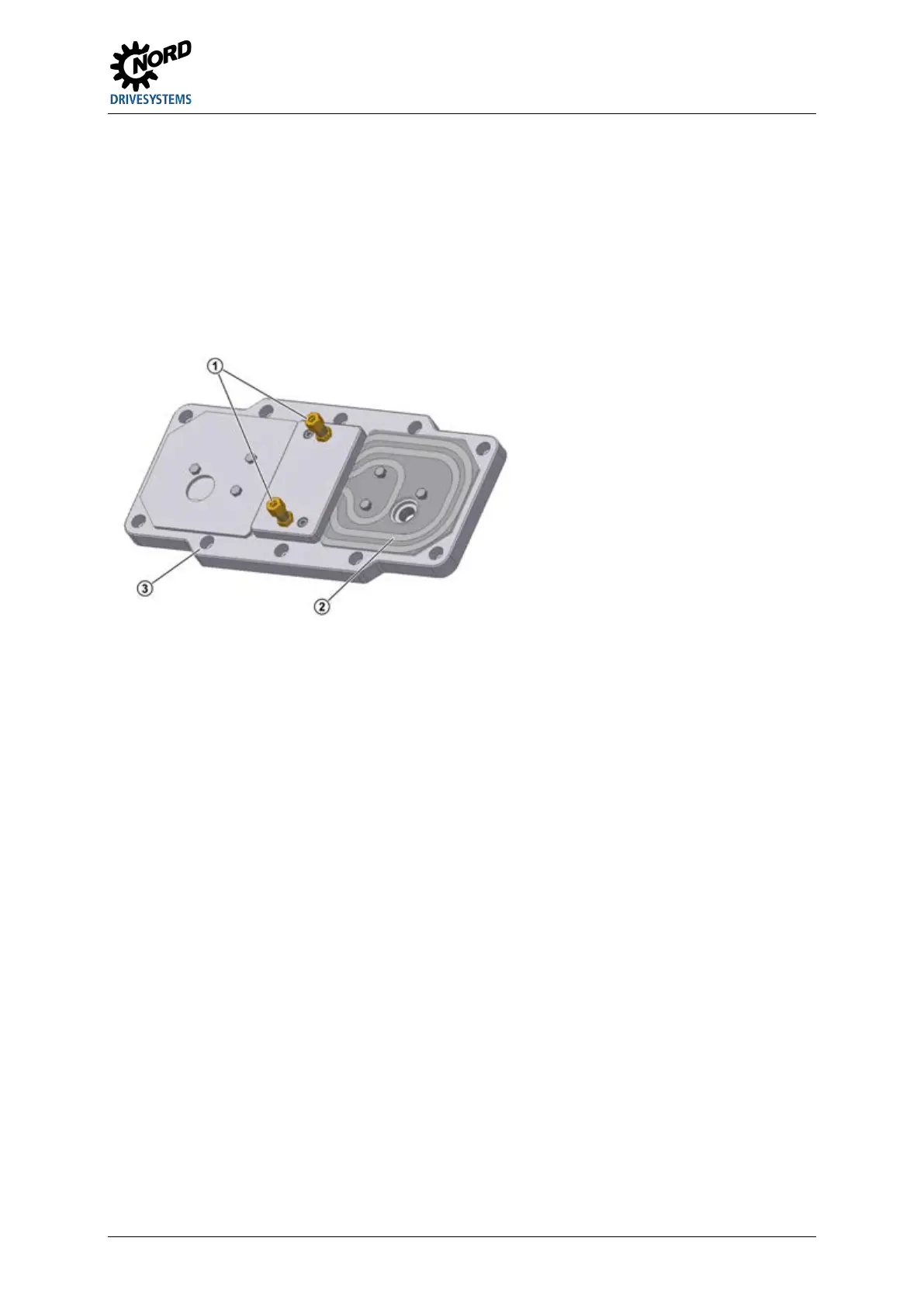
3.12 Fitting the cooling coil to the cooling system
The cooling coil is installed in the housing cover. Cutting ring screw threads according to DIN 2353 are
located at the casing cover for the connection of a pipe with an external diameter of 10 mm.
Remove the closing cap from the screw neck prior to assembly to avoid any contamination of
the cooling system. The screw necks should be connected with the coolant circuit, which must be
provided by the operator. The flow direction of the coolant is irrelevant.
Make sure not to twist the screw necks during or after assembly as the cooling coil may be
damaged. It must be ensured that no external forces act on the cooling coil.
Explanation
Cutting ring screw threads
Figure 20: Cooling cover
Pos: 14 9 /Allg emein/ Allg emeing ültig e Mod ule/---------Sei tenumbr uch ko mpakt --------- @ 13\mod_1476369695906_0.docx @ 2265495 @ @ 1
 Loading...