Gear units – Operating and Assembly Instructions
30 B 1000 en-4419
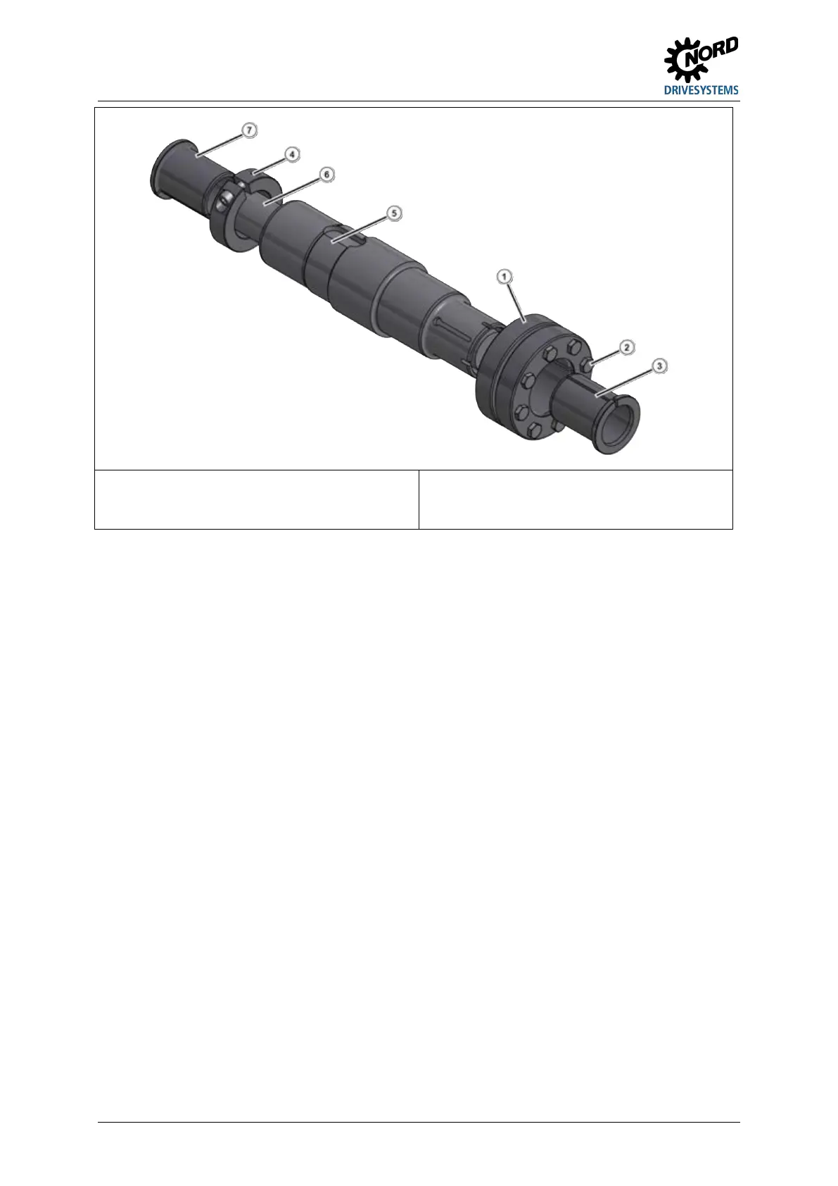
Figure 16: GRIPMAXX™, exploded diagram
1. Carefully examine the solid shaft [6] and remove burrs, rust, corrosion, lubricants or other foreign
bodies. Ensure that the diameter is within the tolerances stated in the table above.
2. Determine the correct installation position of the shrink disc [1] on the gear unit. Ensure that the
position of the hollow shaft [5] corresponds to the details in the order.
3. Remove all contamination, grease or oil from the hollow shaft [5], the bushes [3], [7], the clamping
ring [4] and the shrink disc [1]. Do not use corrosion protection, assembly paste or other
coatings on the fitting surfaces of the shaft, the bushes, the clamping rings or the shrink disc.
4. Bring the clamping ring [4] and the support bush into the correct position on the solid shaft [6] and
ensure that the support bush is in the correct location. Then secure the support bush [7] with the
clamping ring [4] and tighten the clamping ring bolt.
5. Push the gear unit up to the stop against the secured support bush [7] on the solid shaft [6].
6. Ensure that the shrink disc [1] and the torque bush [3] are in the correct position. Only tighten the
shrink disc when the solid shaft [6] and the torque bush [3] are in the correct position, as
otherwise the hollow shaft [5] will be damaged. Tighten the 3 or 4 clamping bolts [2] finger tight
and ensure that the outer rings of the shrink disc are pulled together parallel. Finally, tighten the
remaining bolts.
7. Tighten the tensioning bolts successively in a clockwise direction by several turns - not crosswise
– with approx. ¼ rotation of the bolt per turn. Use a torque wrench to achieve the specified
tightening torque on the shrink disc.
When the tensioning bolts have been tightened, there must be an even gap between the clamping
flanges. If this is not the case, dismantle the shrink disc connection and check the fit.
 Loading...