3 Assembly instructions, storage, preparation, installation
B 1000 en-4419 37
Pos: 15 9 /Anlei tung en/G etrieb e/3. Mo ntag e, Lager ung, V orber eitung, Aufs tell ung/M on tag e/M ont age eine s Öl a usgl eic hsbe hält er Opti on O A @ 10 \mod_1457530404115_388.docx @ 312366 @ 2 @ 1
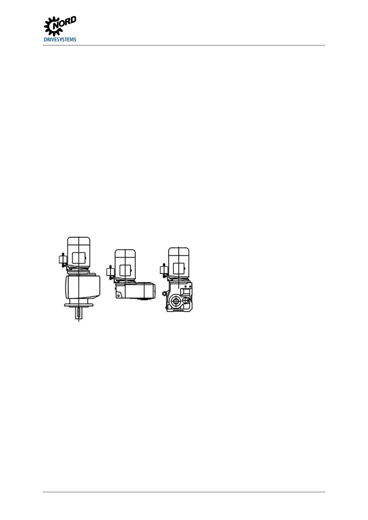
3.14 Installation of an oil expansion tank, Option OA
The expansion tank must be installed vertically with the hose connection facing downwards and the
vent plug upwards. If the tank is not fitted, observe the following steps for fitting:
• After installing the gear unit (motor), remove the vent screw on the gear unit.
• For modules 0.7 l, 2.7 l and 5.4 l the reduction / extension is screwed in with the
existing sealing ring.
• Now fit the expansion tank (see below for suggested position).
Note: If the necessary screw insertion depth of 1.5d can no longer be achieved, use a
5 mm longer screw. If a longer screw cannot be fitted, use a stud and a nut with
appropriate dimensions.
If the fastening screw is screwed into a through hole, seal the thread with a medium
strength screw securing material such as LOXEAL 54-03 or Loctite 242.
• The tank should be fitted as high as possible. - Note the length of the hoses!! -
• After this, fit the vent hose with the enclosed hollow screws and seals.
Finally, screw the enclosed M12x1.5 vent screw and sealing ring into the tank.
Notice: For ATEX gear units, screw the enclosed M12x1.5 vent screw into the tank.
Figure 22: Installing the expansion tank
Pos: 18 0 /Anlei tung en/G etrieb e/3. Mo ntag e, Lager ung, V orber eitung, Aufs tellung /Nac hträgl iche L acki erung /Nachtr ägl iche Lac kieru ng 00 hea dline @ 34\mod_1559724373206_388.docx @ 2538900 @ 2 @ 1
3.15 Subsequent painting
Pos: 18 2 /Anlei tung en/G etrieb e/3. Mo ntag e, Lager ung, V orber eitung, Aufs tellung /Nac hträgl iche L acki erung /Nachtr ägl iche Lac kieru ng 02 @ 34\ mod_1559724405678_388.docx @ 2538974 @ @ 1
For retrospective painting of the gear unit, the shaft sealing rings, rubber elements, pressure vent
screws, hoses, type plates, adhesive labels and motor coupling components must not come into
contact with paints, lacquers or solvents, as otherwise the components may be damaged or made
illegible.
Pos: 18 4 /Anlei tung en/G etrieb e/4. In betri ebna hme/4 . Inbetri ebn ahme [_Ti tel] @ 3\ mod_1368691822868_388.docx @ 65671 @ 1 @ 1
 Loading...