5 Service and maintenance
B 1000 en-4419 43
At the first oil level check a small amount of oil may escape, as the oil level may be above the lower
edge of the oil level hole.
3. Gear units with oil level screw: The correct oil level is at the bottom edge of the oil level hole. If
the oil level is too low, this must be corrected with the appropriate type of oil. Optionally, an oil level
glass is also possible instead of the oil level screw.
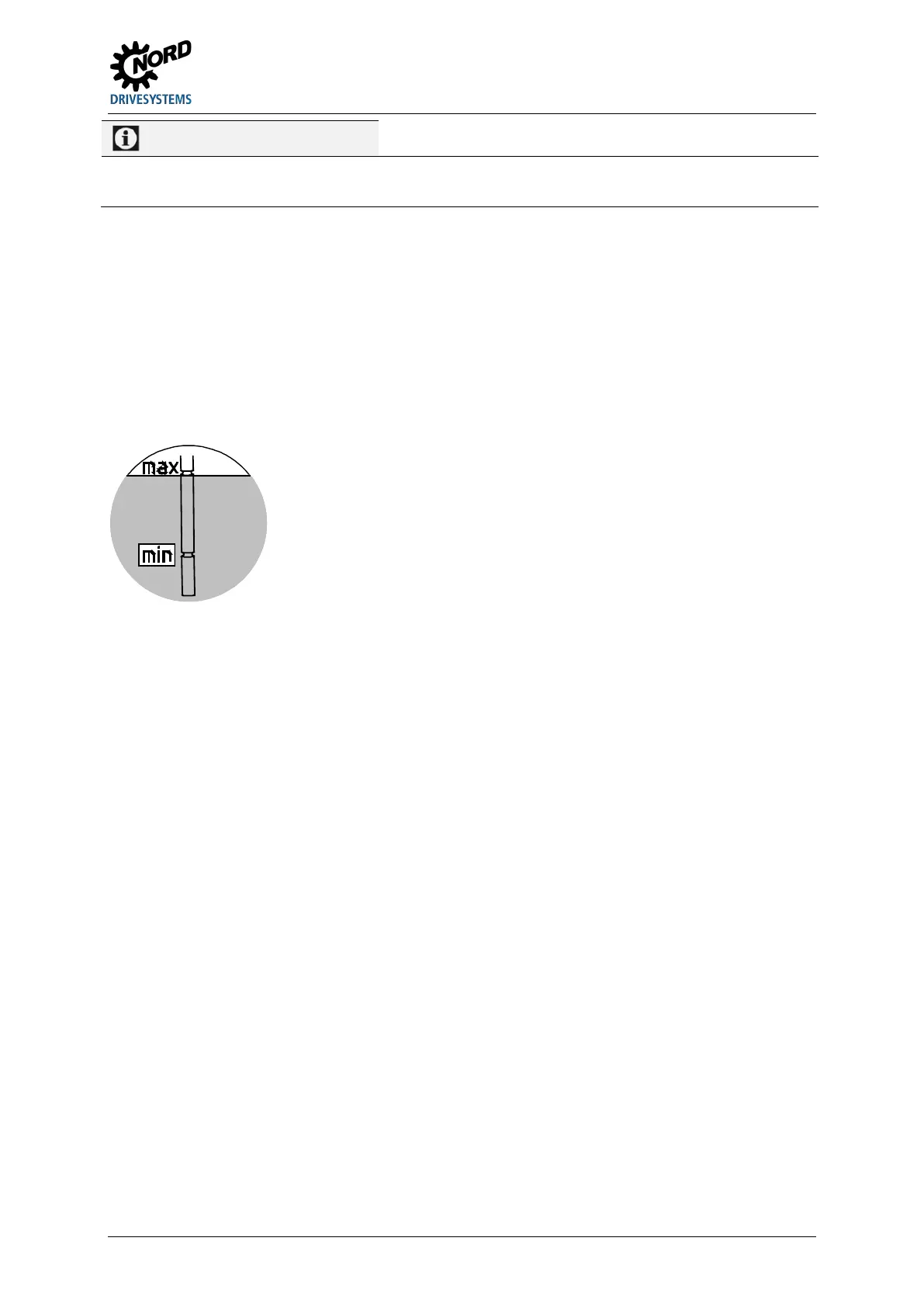
4. Gear units with oil tank: Der The oil level must be checked with the aid of the cap screw with
dipstick (G1¼ thread) in the oil tank. The oil level must be between the top and bottom marking
when the dipstick is fully screwed in (see Figure 26). Top up the oil level with the relevant type of oil
as necessary. These gearboxes may only be operated in the mounting position stated in
Section 7.1 "Versions and maintenance".
5. The oil level screw or the cap screw with dipstick and all other loosened screws must be correctly
re-tightened.
Figure 26: Checking the oil level with a dipstick
Pos: 27 7 /Anlei tung en/G etrieb e/5. In spekti on un d Wartu ng/Ins pekti ons- un d Wartu ngs arbeite n/Ins pekti ons- und Wartungsarbeiten_04a_Sichtkontr oll e Gu mmi puf fer [B2 000] @ 27\mod_1548837240917_388.docx @ 2483414 @ 5 @ 1
Visual inspection of the rubber buffers
Gear units with rubber buffers (Option G or VG) and gear units with torque supports are equipped with
rubber elements. If these show damage such as tears to the rubber surface, the elements must be
replaced. Please contact the NORD service department.
Pos: 285 /A nleit unge n/Getri ebe/ 5. Insp ektion und War tung/I nspe ktions - und W artung sarb eiten/ Insp ektions - und Wartu ngsarb eite n_04b _Sicht kontr olle Sc hlauc h @ 27\mod_1548838386536_388.docx @ 2483461 @ 5 @ 1
Visual inspection of hose
Gear units with an oil tank (Option OT) and external cooling units have rubber hoses. Check the
connections for leaks. After assembling the oil lines, fill the gear unit housing with the gear oil type and
quantity that is printed on the type plate. Please contact the NORD service department.
Pos: 29 6 /Anlei tung en/G etrieb e/5. In spekti on un d Wartu ng/Ins pekti ons- un d Wartu ngs arbeite n/Ins pekti ons- u nd Wart ung sarb eit en_ 05_F ett nac hsc h mier en @ 25\ mod_1544081994869_388.docx @ 2469192 @ 5 @ 1
Re-greasing
Some gear unit designs (free drive shaft, Option W, agitator designs VL2 and VL3) are equipped with
a re-greasing device.
For agitator versions VL2 and VL3, the vent screw located opposite to the grease nipple must be
unscrewed before re-greasing. Grease should be injected until a quantity of 20 - 25 g escapes from
the vent hole. After this, the vent plug must be reinserted and tightened.
For Option W and some IEC adapters, the outer roller bearing must be re-greased with approx.
20 - 25 g of grease via the grease nipple provided. Remove any excess grease from the adapter.
Recommended grease: Petamo GHY 133N (please see chapter 7.2 "Lubricants")(Klüber Lubrication),
a food compatible grease is possible as an option.
 Loading...