Gear units – Operating and Assembly Instructions
44 B 1000 en-4419
Pos: 29 9 /Anlei tung en/G etriebe/5. Inspektion und Wartung/Inspektions- un d Wartu ngsar beite n/Ins pekti ons- und Wartungsarbeiten_06_automatischen Schmierstoffgeber auswechseln @ 25\mod_1544082049733_388.docx @ 2469240 @ 5 @ 1
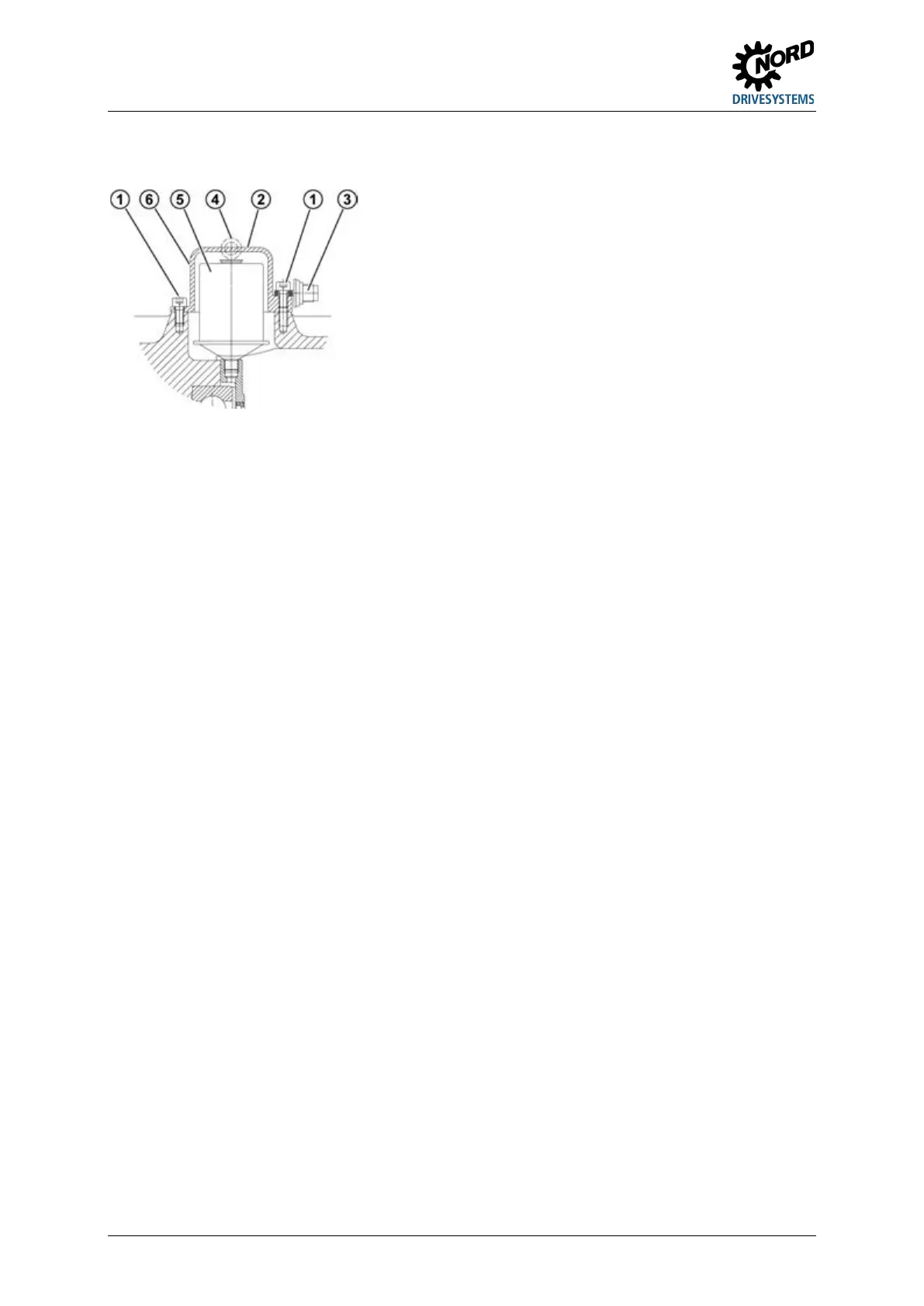
Replacing the automatic lubricant dispenser
Explanation
Cylindrical screws M8 x 16
Position of adhesive label
Figure 27: Replacing the automatic lubricant dispenser with standard motor mounting
The cartridge cover must be unscrewed. The lubrication dispenser is screwed out and replaced with a
new component (Part No. 28301000 or for food-compatible grease Part No.: 28301010). Remove any
excess grease from the adapter. Then activate (please see chapter 4.2 "Activating the automatic
lubricant dispenser").
Empty or replace the grease collection container (Part No. 28301210) with every second replacement
of the lubricant container. To empty the container, unscrew it from the screw fitting. The container has
an internal piston, which can be pressed back with a rod with a maximum diameter of 10 mm. Collect
the grease which is pressed out and dispose of it correctly. Due to the shape of the container, a
residual quantity of grease remains in the container. After emptying and cleaning the container, it can
be screwed back into the drain hole in the IEC adapter. Replace the container with a new one if it is
damaged.
Pos: 30 1 /Anlei tung en/G etrieb e/5. In spekti on un d Wartu ng/Ins pekti ons- un d Wartu ngs arbeite n/Ins pekti ons- und Wartungsarbeiten_07_Öl wechseln [B1000] @ 25\mod_1544082093418_388.doc x @ 24692 88 @ 5 @ 1
Change the oil
The figures in Section 7.1 "Versions and maintenance"show the oil drain screw, the oil level screw and
the pressure vent screw for various designs.
Procedure:
1. Place a catchment vessel under the oil drain screw or the oil drain tap.
2. Completely remove the oil level screw or screwed sealing plug with dipstick if an oil level tank is
being used and unscrew oil drain screw.
3. Drain all the oil from the gear unit.
4. If the sealing ring of the oil drain screw or oil level screw is damaged in the thread, a new oil level
screw must be used or the thread must be cleaned and coated with securing lubricant, e.g.
Loctite 242, Loxeal 54-03 prior to insertion.
5. Screw the oil drain screw into the hole and tighten to the correct torque (please see chapter 7.4
"Screw tightening torques").
6. Using a suitable filling device, refill with oil of the same type through the oil level hole until oil
emerges from the oil level hole. (The oil can also be filled through the pressure vent screw or a
sealing plug located higher than the oil level). If an oil level tank is used, fill the oil through the
upper inlet (thread G1¼) until the oil level is set as described in Section 5.2 "Service and
Maintenance Work".
7. Wait at least 15 minutes, or at least 30 minutes if an oil level tank is used, and then check the oil
level. Proceed as described in Section 5.2 "Service and Maintenance Work".
 Loading...