NORDAC FLEX (SK 200E ... SK 235E) – Brief instructions for Frequency Inverters
28 BU 0240 en-US-4920
Pos: 102 /A nleit ung en/El ek tr onik /FU und Star ter /2. M ontag e u nd I nst alla tio n/Z ube hör/ Brem swi der st and/ SK 1x 0E , SK 2xx E/Br em swi der stan d ( BW) (Üb ersc hrif t + ) [ SK 1x 0E, SK 2xx E] @ 1\mod_1342513979710_14638.docx @ 32689 @ 2 @ 1
2.2 Braking resistor (BW) - (from size 1)
During dynamic braking (frequency reduction) of a three-phase motor, electrical energy is fed back to
the inverter if necessary. From size 1 and above, an internal or external braking resistor can be used
to avoid a shutdown of the device due to overvoltage. The integrated brake chopper (electronic switch)
sheds the excess DC link voltage (operating point approx. 420 V/720 V
DC
, depending on line voltage)
to the braking resistor. The braking resistor converts excess energy into heat.
Pos: 10 3 /Anlei tung en/El ektr onik/FU und Star ter/1 . Allg emei nes/Sic herh eits- und Ins tall ations hinwei se un d Warn- Gefahrenhinweise/neu/Warn- un d Gefa hrenhi nweis e/VOR SICHT - Hei ße O ber fläc he n ( Brems wi ders tan d) @ 2 8\mod_1551424569795_14638.docx @ 2493080 @ @ 1
Hot surfaces
The braking resistor and all other metal components can heat up to temperatures above 70°C.
• Risk of injury due to local burns on contact.
• Heat damage to adjacent objects
Allow sufficient cooling time before starting work on the product. Check the surface temperatures with
suitable measuring equipment. Maintain an adequate distance to adjacent components.
Pos: 104 /A nleit ung en/El ek tr onik /FU und Star ter /2. M ontag e u nd I nst alla tio n/Z ube hör/ Brem swi der st and/ SK 1x 0E , SK 2xx E/IN FOR MA TION - Dat en Br em swi ders ta nd p aram etr ier en [ SK 2 00E ] @ 21\mod_1528383930708_14638.docx @ 2424921 @ @ 1
Parameterization of braking resistor data
To protect the braking resistor from overload, the electrical characteristics of the braking resistor must be
parameterized in parameters P555, P556 and P557. With use of an internal braking resistor (SK BRI4-…) this is
done by setting the DIP switch S1:8 ( Section 2.2.1)
Pos: 105 /A nleit ung en/El ek tr onik /FU und Star ter /2. M ontag e u nd I nst alla tio n/Z ube hör/ Brem swi der st and/ SK 1x 0E , SK 2xx E/In ter ner Br emsw id erst and SK BR I4-. .. [S K 2xxE] @ 21\mod_1528365342363_14638.docx @ 2424697 @ 35 @ 1
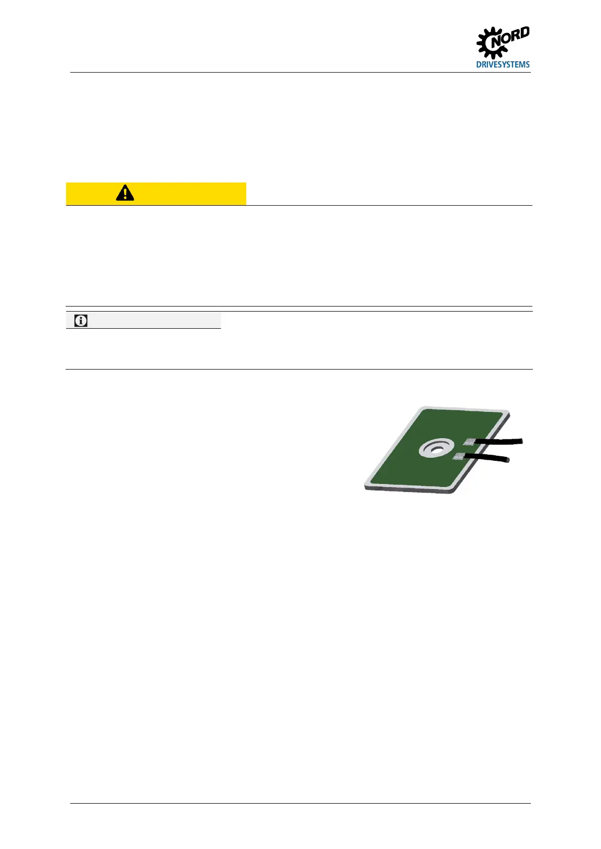
2.2.1 Internal braking resistor SK BRI4-…
The internal braking resistor can be used if only slight, short
braking period are to be expected. The item includes a set of
2 braking resistors in the individual rating classes of size 4.
These must be connected in parallel and thereby satisfy the
electr
ical data from the description of the material. The
mounting location for the 2nd braking resistor is opposite the
mounting location of the 1st braking resistor.
Similar to illustration
 Loading...


